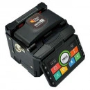
FiberFox Mini 3S Active Alignment Splicer
Fusion Splicers
Product Description
Splicing Method: Active alignment(4motors)Average Loss: SM:0.03dB/MM:0.02dB/DS:0.05dB/NZDS:0.05dB/G.657:0.03dBReturn Loss: >>60dBSplice Time: 8sElectrode Lifespan: 3500+ arcs
PRODUCT BROCHURE
Specifications
Splicing Method: Active alignment(4motors)Average Loss: SM:0.03dB/MM:0.02dB/DS:0.05dB/NZDS:0.05dB/G.657:0.03dBReturn Loss: >>60dBSplice Time: 8sElectrode Lifespan: 3500+ arcsApplicable Fibers: SM(ITU-T G.652&G.657)/MM(ITU-T G.651)/DS(ITU-T G 653)/NZDS(ITU-T G.655)Illumination: Red LED 2 ea, White LED 2eaCleaved Length: (coating)/cleave length 5~16mmCoating Diameter: 100-1000umCladding Diameter: 80um ~ 150umHeating Programs: Total 32 heating modes, preset 5 heating modesHeating Time: 18sProtection Sleeve: 40mm,60mm,SOC-3.0, SOC-0.9Data Output: USB 2.0(Mini-B type) Connector for PC CommunicationSplice Programs: Total 128 splice modes, preset 11 splice modesSplice Memory: 10,000 recordsBattery: 3,000mAh / Typical 180 cycles of splice / heating per battery full chargePower Supply: AC:100 ~ 240V DC:9 ~14VMonitor: 4.3 inches monitorCameras: 2 CCD camera systemMagnification: 130X magnification with 3 display modes, 260X partial magnificationFiber Display: X/Y or XY, single X, YWeight: 1.35kg(include battry)Size: 123mm x 114mm x 126mmWind Protection: The max wind speed 15m/sOperating Environment: Elevation 0-5,000 meter, -10~50 , 0~95%RH relative humidityStorage Condition: Temperature -20 to 60 , 0~95%RH relative humidity, battery -20~40Pull Test: 1.96~2.25N (standard)

20W Portable LED Work Light Cordless Rechargeable LED Flood Light
Miscellaneous
Product Description
• Slim Line 20w Power Hand Lamp, LED Day Light 6500K• Excellent Professional for Photographers Tradesmen, DIY a like.• 20w Portable LED Work Torch Light Rechargeable Flood Light IP65• Car cigarette lighter charger use in the car or changing, Multi position handle/adjustable stand
ZAR 400.00
ZAR 500.00
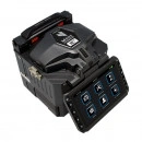
FiberFox Mini 5C+
Fusion Splicers
Product Description
The Most Complete Fusion Splicer KitCore Alignment Splicer w/ Fixed Focus
Size: 4.8 x 4.88 x 5.4 (in)Weight: 2.88lbs. (w/o battery)
Fastest Splicing Time6 sec with single mode fiber (quick mode)10 sec Heating time* 6 sec with continuous heating mode
Comes with 2 Battery PacksFull Touch ScreenSOC Compatible
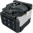
FiberFox Mini 6S+ WiFi Splicer Kit
Fusion Splicers
Product Description
The Mini 6S+ comes with all the same excellent specification as the Mini 6s Core Alignment Fusion Splicer but with extra enhancements so that users spends even less time on each termination. This unit is still the same compact size for convenient transportation and storage & comes with a full range of accessories and spares.
01MINI 6S+ Splicer
04 Power Cord
07 Car Cigar Cable
10 SOC Heater Block
13 Shoulder Strap
02 MINI 50G+ Cleaver
05 USB Cable
08 Cooling Tray
11 SOC Holder
14 User Manual CD
03 Cleaver Softcase
06 AC Adapter
09 Spare Electrode
12 2 Battery Packs
15 Hand Carrying Case
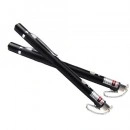
Red Laser Light Source Visual Fault Locator
Visual Fault Locator
Product Description
Red laser Light Source visual fault locator exfo otdr transmitter tv test vfl-650 fiber optic cable tester.
Power Output :10mW
ZAR 570.00
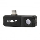
UNI-T UTi120 Mobile Thermal Imager (Android)
Temperature
Product Description
UTi120M is a professional smartphone thermal camera module for Android, which is compact, portable, and easy to operate through connecting with mobile phones. UTi120M rovides clear image with a fast response, and can also detect temperature up to 400℃. Users can troubleshoot HVAC problems or investigate heat source issues around the house faster and easier with this thermal camera module.
It is a perfect tool for DIY homeowners,outdoor lovers, engineers, contractors and builders etc.
Smartphone Thermal Camera Module for Android
Features :
IR resolution: 120×90
Temperature measurement range: -20℃ to 400℃ / -4℉ to 752 ℉
Auto alarm for high/low temperature
Auto tracking for hot spot/cold spot
On display screen analyzer: 6 Points/6 Lines /6 Rectangles/6 Circles
Image capture
Video recording
Color palettes: 7 (White hot, Black hot, Red hot Ironbow, Lava, Rainbow, Rainbow HC)
Phone: Android (USB Type-C interface)
1m extension cable
1m drop proof
Product Specifications of UTi120M
Technical Data
IR resolution (Pixels)
120×90
Field of view(FOV)
50°×38°
Thermal sensitivity(NETD)
≤60mK @25℃
Spatial resolution(IFOV)
7.3mrad
Frame rate
≤25Hz
Focus
Focus free
Lens focal length
2.28mm
Temperature measurement range
-20℃ ~ 400℃
Accuracy
±2℃ or ±2%whichever is greater
Emissivity
0.01~1.00 adjustable (0.95 default)
Functions
Color palettes
7(White hot, Lava, Ironbow,Black hot, Red hot, Rainbow, Rainbow HC)
Image modes
Thermal,Fusion,PIP
On screen analyzer
6 Points/6 Lines/6 Rectangles/6 Circles
Hi/Lo temperature alarm
√
Video recording
√
General Characteristics
USB
Type-C
Drop proof
2m
Image/Video storage format
JPEG, MP4
Certificates
CE,UKCA,FCC,RoHS
Languages
ZH, EN
Product net weight
25g
Product size
53mm×18.2mm×18.5mm
Packing Details
Standard accessories
Micro USB adapter, USB cable, English manual, Documents download operation guide card
Standard individual packing
Gift box
Standard Qty per carton
20pcs
Standard carton size
290mm×265mm×325mm
Standard carton G.W.
4.8kg
ZAR 4,700.00
ZAR 5,000.00
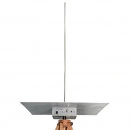
TBMA5 Active Monopole Antenna
TEKBOX ANTENNAS
Product Description
The TBMA5 is an active Monopole Antenna, expanding the Tekbox product range of affordable EMC pre-compliance test equipment.The monopole antenna is designed for radiated emission measurements within the frequency range 9 kHz – 30 MHz, according to CISPR 16. The monopole antenna has a rod with a height of 104 cm and provides sufficient sensitivity to carry out radiated emission measurements as specified in CISPR 25 or MIL-STD-461G.
The TBMA5 consists of an impedance converter, a universal charger, a 10 mm diameter rod, a 60 cm x 60 cm ground plane and a standard 10pF calibration adapter. Furthermore, it includes the coaxial cable with ferrite and grounding equipment required under MIL-STD-461G. The impedance converter is equipped with a ¼” thread to attach it to conventional tripods.
SPECIFICATIONS
Characterized frequency range: 9 kHz to 30 MHz
Electric field antenna factor: +6 to +7 dB/m, typ.
Antenna factor variation: < ±0.8 dB, typ.
Dynamic Range: 118 dB @ 1MHz, 1 KHz bandwidth
Electric field, lower limit: 12 dBµV/m (4.0 µV/m) @ 1MHz, 1 KHz bandwidth
Electric field, upper limit: 130 dBµV/m (3.15 V/m) @ 1 dB compression
Output VSWR: 1.02 to 1.52 (average:1.06) :1
Output connector type: N female
Battery type: 6 x NiMH, AA (not included)
Battery life on average: 20 hours
Charger: Ansmann ACS310
Tripod mount: ¼” thread
Impedance converter dimensions: 185 x 210 x 65 mm, 1.5 kg
Carrying Case: Aluminum, 75 x 73 x 18 cm, 4 kg
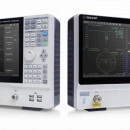
SNA5000A Series Vector Network Analyzer
Vector Network Analyzers
Product Description
The SIGLENT SNA5000A series of Vector Network Analyzers have a frequency range of 9 kHz to 8.5 GHz and 100 kHz to 26.5 GHz, which support 2/4-port scattering parameter, differential-parameter, and time-domain parameter measurements. The SNA5000A series of VNAs are effective instrumentation for determining the Q-factor, bandwidth, and insertion loss of a filter, They feature impedance conversion, movement of measurement plane, limit testing, ripple test, fixture simulation, and adapter removal/insertion adjustments. The VNAs have five sweep types: Linear-Frequency mode, Log-Frequency mode, Power-Sweep mode, CW-Time mode, and Segment-Sweep mode. The SNA5000A series VNAs also support scattering-parameter correction of SOLT, SOLR, TRL, Response, and Enhanced Response for increased flexibility in R&D and manufacturing applications.
Key Features
Frequency range: 9 kHz – 8.5 GHz and 100 kHz – 26.5 GHz
Frequency resolution: 1 Hz
Level resolution: 0.05 dB
Range of IFBW: 10 Hz~3 MHz
Setting range of output level:-55 dBm ~ +10 dBm
Dynamic range: 125 dB
Types of calibration: Response calibration, Enhanced Response calibration, Full-one port calibration, Full-two port calibration, Full-three port calibration, Full-four port calibration, TRL calibration
Types of measurement: Scattering-parameter measurement, differential-parameter measurement, receiver measurement, time-domain parameter analysis, limit test, ripple test, impedance conversion, fixture simulation, adapter removal/insertion, spectrum analysis frequency offset, scalar mixer measurement
Internal Bias-Tee connections
Interface: LAN, USB Device, USB Host (USB-GPIB)
Remote control: SCPI/ Labview/ IVI based on USB-TMC / VXI-11 / Socket /Telnet / WebServer
1-inch touch screen
Video output: HDMI
SNA5002A
9 kHz~4.5 GHz
2
125 dB
0.003 dB rms,0.03° rms
-55 ~ +10 dBm
SNA5004A
9 kHz~4.5 GHz
4
125 dB
0.003 dB rms,0.03° rms
-55 ~ +10 dBm
SNA5012A
9 kHz~8.5 GHz
2
125 dB
0.003 dB rms,0.03° rms
-55 ~ +10 dBm
SNA5014A
9 kHz~8.5 GHz
4
125 dB
0.003 dB rms,0.03° rms
-55 ~ +10 dBm
SNA5022A
100 kHz~13.5 GHz
2
125 dB
0.003 dB rms,0.03° rms
-55 dBm ~ +10 dBm
SNA5032A
100 kHz~26.5 GHz
2
125 dB
0.003 dB rms,0.03° rms
-55 dBm ~ +10 dBm
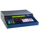
Univesal IC Tester + LCR Meter
Miscellaneous
Product Description
68032 is the latest Micro controller based Universal IC Tester with LCR Meter. It functionally tests 74 series of TTL ICs 40 & 45 series of CMOS IC, Analog/ Linear ICs opamps, comparators, timers, transistor arrays, ADC, DAC etc
SPECIFICATION
68032 is the latest Micro controller based Universal IC Tester with LCR Meter. It functionally tests 74 series of TTL ICs 40 & 45 series of CMOS IC, Analog/ Linear ICs opamps, comparators, timers, transistor arrays, ADC, DAC etc., It also tests components like diode, transistors, UJT, FET, SCR, Displays, regulators, (78/79) and DIP relays. It also measures the values of Inductance (L), capacitance (C) and Resistance (R). 68032 has RS 232 Serail interface through which IC Test Library could be expanded.
Digital IC Tester to test Digital ICs TTL/ CMOS (14/16/20 Pins)
Analog IC Tester to test Linear/ analog ICs (4, 6, 8, 14, 20 Pins)
LCR Meter - Measures L, C, R, with Calibration Facility
Micro controller Development System
Serial Port for Upgradation
Buzzer for Bad IC indication.
Components Tester to test Diode, Transistors, SCR, UJT, FET Regulator & Displays
Technical Specification
Display : 40x2 Backlit Alphanumeric LCD
Keyboard : 24 keys Membrane Keyboard
Socket :
20 Pin ZIF Socket for DIP ICs Components Holder/ Machine base for D/L/C/R
3 pin Machine base for Transistors, UJT, FET, SCR
3 pin Machine base for 78XX/ 79XX Regulator
Test Range : Digital & Linear ICs, 6, 8, 14, 16, 20 Pin in DIP Pack. Active & Passive Components
Enclosure : Sheet Metal Cabinet with powder coating and Engraving
Voltage : 230VAC 50 Hz ± 10%
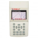
Solar Module / Solar System Analyzer (Photovoltaic I-V Curve Tester)17714C
Educational Equipment
Product Description
Solar Module / Solar System Analyzer (Photovoltaic I-V Curve Tester) : Solar System Analyzer (Photovoltaic I - V Curve Tester) with DC Current Clamp, AC Power Clamp, Thermo & Irradiance Meter (with Bluetooth Connectivity) : Max. Solar System Power Search by Auto Scan : 1000V DC, 12A DC (12 KW Capacity), Measures Single Panel and String OPC and STC Data with Vnow, Voc, Isc, Pmax, VmaxP, ImaxP, Efficeincy and Fill Factor, Real Time Irradiation and Solar Panel Temperature, Inverter Efficiency (DC to AC) with PC (USB) Connectivity, Memory Record and Backlight Dispaly O Environment
SPECIFICATION
Solar Module / Solar System Analyzer (Photovoltaic I-V Curve Tester) : Solar System Analyzer (Photovoltaic I - V Curve Tester) with DC Current Clamp, AC Power Clamp, Thermo & Irradiance Meter (with Bluetooth Connectivity) : Max. Solar System Power Search by Auto Scan : 1000V DC, 12A DC (12 KW Capacity), Measures Single Panel and String OPC and STC Data with Vnow, Voc, Isc, Pmax, VmaxP, ImaxP, Efficeincy and Fill Factor, Real Time Irradiation and Solar Panel Temperature, Inverter Efficiency (DC to AC) with PC (USB) Connectivity, Memory Record and Backlight Dispaly O Environment
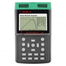
Solar Module / Solar System Analyzer (Photovoltaic I-V Curve Tester) 17714
All Educational Equipment
Product Description
Solar Module / Solar System Analyzer (Photovoltaic I-V Curve Tester) : Solar Module Analyzer (Photovoltaic I - V Curve Tester) : 60V, 12A (500W Capacity), Measures : Vnow, Voc, Isc, Pmax, VmaxP, ImaxP, Efficeincy and Fill Factor
SPECIFICATION
Solar Module / Solar System Analyzer (Photovoltaic I-V Curve Tester) : Solar Module Analyzer (Photovoltaic I - V Curve Tester) : 60V, 12A (500W Capacity), Measures : Vnow, Voc, Isc, Pmax, VmaxP, ImaxP, Efficeincy and Fill Factor with PC Connectivity, Memory Record and Backlight Display
Product Specification (Click Here)
Solar System Analyzer: Everything You Want to Know About It
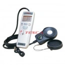
Solar Module / Solar System Analyzer (Photovoltaic I-V Curve Tester)
All Educational Equipment
Product Description
Solar Module / Solar System Analyzer (Photovoltaic I-V Curve Tester) : Solar Power Meter (Irradiance Meter) with Orientation and Tilt Angle : 0 - 90°, Irradiance Range : 0-2000 W/m2 (0 - 634 BTU / ft2.h) with Data Hold and Backlight Display
SPECIFICATION
Solar Module / Solar System Analyzer (Photovoltaic I-V Curve Tester) : Solar Power Meter (Irradiance Meter) with Orientation and Tilt Angle : 0 - 90°, Irradiance Range : 0-2000 W/m2 (0 - 634 BTU / ft2.h) with Data Hold and Backlight Display
Product Specification (Click Here)
Solar System Analyzer: Everything You Want to Know About It
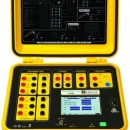
PHOTOVOLTAIC-TEST FTV500
Power Monitoring
Product Description
PHOTOVOLTAIC-TEST FTV500 – 5 measurements in a single instrumentMULTIFUNCTION TESTER FOR SINGLE-PHASE, THREE-PHASE AND MULTI-STRING PHOTOVOLTAIC INSTALLATIONS Performance, maintenance and electrical safety
Description
The PHOTOVOLTAIC-TEST FTV500 is a portable instrument designed to meet all the needs of technicians and professionals involved in commissioning, inspection and maintenance of photovoltaic systems.This instrument measures and analyses all the parameters and characteristics of single or three-phase systems (3 DC current clamps + 3 AC current clamps), in compliance with the applicable international standards. The Photovoltaic-test ftv500's large data storage capacity, data recording function and remote control using Virtual Network Computing (VNC) technology, make it a portable on-site instrument providing a comprehensive system for your scheduled maintenance campaigns.
EFFICIENCY, PERFORMANCE AND DATA LOGGER(IEC 62446)It offers 3 DC current and voltage inputs and 3 AC current and voltage inputs for detailed measurements on the whole photovoltaic installation. It measures DC/AC conversion efficiency, the active and theoretical power values and the phasor diagram at the outputs from the converter. Each parameter is correlated with the irradiation quantities, the ambient temperature and the panel temperature, which are measured with the remote control unit. The results are then compared with the regulatory reference values.
I-V CURVE, I-V QUICK CHECK (IEC 62446, IEC 60891 )The FTV500 analyses the I-V curve and the characteristics of the panels and/or strings up to 1,000 V and 20 A and compares them with the STC reference values indicated by the manufacturer.The instrument uses a 4P connection to manage the measurement autonomously and quickly display:- the graphic showing the characteristic curves (voltage/current/power), - the main parameters- the comparison of the measurement results with the STC values, which are taken from an internal database in the photovoltaic modules
This database is updated by the users, who can then integrate the manufacturer specifications for the panels that they wish to add and test.. A quick test function is available: measurement of the open-circuit voltage and the short-circuit current of individual panels or strings in parallel.
INSULATION RESISTANCE / CONTINUITY (IEC 62446, IEC 61557)This measurement can be used to check the electrical safety of the photovoltaic system (module, string or entire system). The FTV500 measures the insulation resistance without a current flowing (megohmmeter), or even on installations in operation (live), without needing an external switch to short-circuit the positive and negative poles. By selecting the test voltage (250-500-1,000 VDC) and programming a PASS-FAIL threshold alarm for the results, you can obtain an immediate result. The continuity check on the protective conductors by means of a 200 mA current complies with the requirements of the international standards.
REMOTE CONTROL, WIFI & VNC TECHNOLOGY, TEST REPORTSPHOTOVOLTAIC-TEST FTV500 is the first portable multifunction unit equipped with VNC (Virtual Network Computing) technology. It allows remote control and management of all the measurement functions directly from your smartphone / PC / tablet.When used with Wifi transmission, it is the ideal solution for remote assistance or for supporting technicians in the field from your office. The instrument's large memory means you can record more than 10,000 measurements and immediately create reports with a single click. With a USB drive, it is possible to download and give access to the database.
REMOTE UNITThe remote unit of the PHOTOVOLTAIC TEST FTV500 collects the readings of the environmental parameters (irradiation, ambient / module temperature) in real time and then uses them to analyse the results. Thanks to Wifi technology, the remote unit seamlessly transmits the data to the instrument at a distance of up to 200 m in open field conditions and, if the transmission signal is interrupted, it enables the instrument to function as a data logger and store the acquired measurements before resynchronizing and transmitting them to the instrument when the conditions return to normal. A patented mounting system offers installation stability and measurement reliability..
GENERAL SPECIFICATIONSDisplay TFT display with 16.7M colours, 5” touch screen with anti-reflective Optical Bonding technology, resolution 800x480Remote unit Real-time Wifi transmission, real-time modes and recording of the data / synchronization if the signal is lostInterface - Instrument: transmission via Wifi and remote control using VNC (Virtual Network Computing), USB- Remote unit: Wifi transmissionData storage- Programmable internal database: sites/installations/companies/panels/measurements, with tree-structure- Backup capacity: more than 10,000 blocks for all the measurements, 600,000 measurements in data recording modePower supply / battery life- Instrument: rechargeable Li-Ion batteries with 100-240V 50-60Hz power supply / 15 hours on standby (programmable)- Remote unit: rechargeable Li-Ion batteries with power supply and USB cable / 15 hours on standbyProtection Instrument and remote unit: IP54Electrical safety Double insulation, IEC 61010-1, Cat. II 1000V to Cat. IV 600V depending on the measurementCompliance with standards IEC 62446, IEC 60891, IEC 60904-5, IEC 61557-2, IEC 61557-4, CEI 82-25, CEI 64-8Dimensions / weight - Instrument: 340 x 300 x 200 mm / approx. 6 kg- Remote unit: 160 x 120 x 63 mm / approx. 1 kg
FTV 500 Brochure
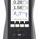
SMP3 Field strength meter
Wavemon Area Monitors
SMP3 Field strength meter
3 INSTRUMENTS IN 1DC Field measurementsSpectrum Analysis – FFT up to 10 MHzBroadband measurements up to 60 GHz
WEIGHTED PEAK METHOD (WPM)Real-time comparison in % with the selected limits up to 10 MHz
ONE SINGLE METER FOR ALL PROBESIsotropic and high accuracy probesElectric and Magnetic fieldProbe auto-detect capability
ASSESSMENTS ACCORDING TO INTERNATIONAL STANDARDSEU Directive 2013/35, ICNIRP, IEC, EN, IEEE, SC6, etc.All limits embedded in a single meter
USB AND FIBER OPTIC COMMUNICATION PC software includedData download, automatic reporting, and remote control
FIRMWARE UPGRADE Easy and fast install to upgrade capabilities
Datasheet_SMP3_EN.pdf
COMPATIBLE FIELD PROBES
3-in-1 Field Meter
The only device that offers genuine 3-in-1 functionalities: broadband measurements (DC to 60 GHz), frequency spectrum analysis (DC to 10 MHz) and static field measurements.The SMP3 field meter provides the most advanced features and technology on the market, designed for users who need high-quality measurements, ease of use and good reporting tools.
SMP3 Field Meter features
3-in-1 Field Meter: spectrum analysis (DC – 10 Mhz), broadband (DC - 60 GHz) and static field measurements.
Real-time FFT-based spectrum analysis using digital processing.
Weighted Peak Method (WPM) for automatic and real time comparison with limits.
Special auto-gain function for peak detection (indispensable for procedures such as welding).
Display of results in RMS and peak values.
Function for time domain measurement of a specific frequency.
Automatic field probe recognition.
E&H field selection.
Total field value and value for each component (X, Y, Z).
Frequency SPAN selection.
High Pass Filters at 1 Hz, 10 Hz, 25 Hz and 100 Hz.
Max-hold function.
Display of maximum, minimum and average values.
Sliding window function according to standards.
Spatial average function.
Adjustable measurement time from 1s to 100 hours.
Programmable measurement to start at a given time.
Graphic display of broadband measurement changes over time.
Adjustable graph display from 1 s to 12 minutes.
Programmable alarm function.
Digital output for real time external measurements.
USB-C and fibre optics connection.
Large storage capacity.
Screen-shot function for reporting.
PC software for control and reporting.
Results can be uploaded automatically to a web-page control centre.
Available in several languages.
Accessories
SMP3 included accessories:
‘SMP Reader’ PC software
SMP3 carrying case
USB Cable
AC/DC charger
SMP3 optional accessories
SMP3-Streamer option
Non-reflective wooden tripod
Tripod extension
Probe support for tripod
Probe extension cable
GPS
Fiber optics interface
SMP3 protective pouch
SMP3 backpack
Vehicle DC charger

MonitEM-Lab Indoor RF monitoring
Wavemon Area Monitors
MonitEM-Lab Indoor RF monitoring
24/7 Monitoring Permanent around the clock monitoring
Alarms Realtime, audible and visual alarms
Broadband measurement For an easy indoor RF monitoring of human exposure
Compliance with ITU-T K.83 Direct, easy and comprehensible comparison with regulated limits
Control center Optional software for system management
MonitEM_Lab_Datasheet_EN.pdf
Compatible Field Probes
E (100 kHz - 60 GHz)
H (300 kHz – 1000 MHz)
RF Monitor overexposure alarms
MonitEM-Lab can warn of a higher than expected electromagnetic field level in different ways: by sending an alarm to the control centre (to be received by the specified e-mail addresses), or by a sound alarm or a light alarm.All the alarms are built in, making the device compact with no need for external accessories. The alarm to the control center is transmitted via ethernet, the audible alarm is internal to the equipment, like the visible alarm, which noticeably illuminates the entire dome of the indoor RF (Radio frequency) monitoring equipment.
control center
MonitEM devices can be optionally used together with a web server using software that is unique on the market and allows remote configuration and management of the monitoring equipment, data consultation and report generation, among other functions.
MANAGEMENT AND CONFIGURATION OF EQUIPMENT
DATA RECEPTION, CONSULTATION AND STORAGE
REPORT GENERATION AND AUTOMATIC DELIVERY
DISPLAY OF PHOTOGRAPHS AND DIAGRAMS
USER FRIENDLY, WITH GOOGLE MAPS POSITIONING
Applications
Defense
Reference customers
ITU-T K.83 Recommendation
Monitoring of electromagnetic field levels.
The ITU-T K.83 Recommendation provides guidelines for taking long-term measurements for control of electromagnetic fields (EMF) in selected areas of public interest, in order to show that those fields are under control and remain with the established limits. The aim of that Recommendation is provide the general public with clear and easily accessible information on electromagnetic fields set out in the form of the results of continuous measurement.
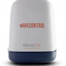
MonitEM Continuous EMF monitor
Wavemon Area Monitors
MonitEM Continuous EMF monitor
24/7 Monitoring Guaranteed autonomy with the “Smart Energy” function (AC + solar panel + battery)
Broadband measurements Up to 3 kHz in LF and 60 GHz in HF
IP 66 environmental protection Resistant to extreme weather conditions
Compliance with ITU-T K.83 Direct, easy and comprehensible comparison with regulated limits
Easy installation Accessories for easy installation in different surroundings
Control Centre Optional software for system management
MonitEM_Datasheet_EN.pdf
Compatible Field Probes
E & H (10 Hz – 3 kHz)
E (100 kHz - 60 GHz)
H (300 kHz – 1000 MHz)
E (Mobile & WiFi)
24/7 Monitoring
Our “Smart Energy” technology provides a combination of AC power with a battery and solar panel. Smart energy management allows uninterrupted, efficient and sustainable operation.The built-in modem allows the remote wireless communication of the continuous EMF monitor with the Control Centre.
Solar panel
Battery
GPRS/3G built-in modem
Easy installation
The EMF monitor is equipped with accessories to make installation easy almost anywhere.The basic criteria for installation are:
Monitoring a specific transmitter: installation near the antenna, if possible, within the direction of maximum radiation, making it reasonable to assume that all other points in the vicinity will have lower levels than those measured.
Monitoring a specific point: installation directly at that point; all radiation reaching that point from every direction is recorded. Examples of special interest points include day-care centres, schools, hospitals, public buildings or offices, industrial facilities, airports, military posts, etc.
Resistant to extreme weather conditions
MonitEM devices have an environmental protection rating of IP 66, the highest in its class. A protection rating of IP 66 is indispensable for EMF monitors that must remain permanently outdoors, exposed to storms and air-borne particles. That high degree of protection ensures that the equipment remains in good working condition for years, reducing maintenance costs, and providing greater reliability.
control center
MonitEM devices can be optionally used together with a web server using software that is unique on the market. It allows remote configuration and management of the monitoring equipment, data consultation and report generation, among other functions. It also offers the option of a public Internet page to display data and compare it easily with regulated limits.
ControlCenter_Datasheet_EN.pdf
MANAGEMENT AND CONFIGURATION OF EQUIPMENT
DATA RECEPTION, CONSULTATION AND STORAGE
REPORT GENERATION AND AUTOMATIC DELIVERY
DISPLAY OF PHOTOGRAPHS AND DIAGRAMS
USER FRIENDLY, WITH GOOGLE MAPS POSITIONING
Continuous EMF monitoring of exposure levels
MonitEM_Datasheet_EN.pdf
Telecommunications
Energy
ITU-T K.83 Recommendation
Monitoring of electromagnetic field levels.
The ITU-T K.83 Recommendation provides guidelines for taking long-term measurements for control of electromagnetic fields (EMF) in selected areas of public interest, in order to show that those fields are under control and remain with the established limits. The aim of that Recommendation is provide the general public with clear and easily accessible information on electromagnetic fields set out in the form of the results of continuous measurement.
Electromagnetic_Field_Levels.pdf
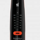
WaveMon LF-400 LF Personal Monitor (DC to 400 kHz)
Wavecontrol : RF safety / EMF safety
WaveMon LF-400 LF Personal Monitor
STATIC FIELD DETECTION
0 Hz - Isotropic hall effect sensor
LOW FREQUENCY DETECTION
10 Hz to 400 kHz - Isotropic coil-based sensor
ACCORDING TO ICNIRP GUIDELINES
For general public and occupational exposure
EXPOSIMETER WITH DATALOGGER
Data collecting and Reporting
GPS AND ALTIMETER
Geolocation of measurements
HIGH INTENSITY AUDIBLE, VISIBLE AND VIBRATORY ALARM
With user definable trigger threshold
USB COMMUNICATION PORT
Data downloading, set-up and battery charging
LF-400_Datasheet_EN.pdf
PUBLIC AND OCCUPATIONAL LIMITS
The WaveMon LF-400 is an exposimeter that warns the user of a high level of exposure to low frequency magnetic fields.
Warnings are given as a percentage of exposure to a defined limit of a specific standard. It can work with general public or occupational limits.
The following exposimeters are now available:
WaveMon LF-400 ICN → For the ICNIRP guidelines
WaveMon LF-400 EUD → For the European EMF Directive 2013/35/EU
WaveMon LF-400 IEEE → For the IEEE standards
If you need a personal low frequency monitor that specifically follows any other standard, please let us know.
DATALOGGER
The WaveMon LF-400 is a low frequency exposimeter that has a datalogger for continuous data recording.
Communication with the device is through a USB port that allows you to configure the device and download the recorded data. This makes it easy to create reports and allows you to keep a record of your exposure data for your safety.
CONVENIENCE AND SECURITY
We have created an accessory that allows you to attach the personal monitor to your harness, arm or belt and so take it in hand to hold it near a radiation source and then put it back in place easily.
You can also secure it with a small carabiner so that it won’t be dropped.
BATTERIES
The device is small and lightweight and works with AA batteries that can be recharged via the USB port. It can also use standard AA batteries, so that they can always be easily replaced.
Easy, isn’t it? Because we want you always to be protected.
GPS AND ALTIMETER
The WaveMon is the only personal monitor equipped with a GPS and Altimeter for geolocation of measurements.
As an example, in a high voltage tower, the GPS will provide the geographical position of the tower and the Altimeter the relative height from the ground.
USER-CONFIGURABLE ALARMS
Over-exposure alarms can be configured from a PC using the USB connection. Two different alarms can be programmed and personalised separately for each of the standards: General Public and Occupational.The alarm level (% of the selected limit) and the type of alarm (sound, vibration or both) can be set-up.
MAIN CHARACTERISTICS OF THE WAVEMON LF-400
Conforms to international electromagnetic field safety standards
H/B-field measurements from 0 Hz to 400 kHz
Isotropic sensors
Weighted response for direct comparison with the standard limit
User-configurable alarms
High intensity audible, visible and vibration alarms
Customisable alarm threshold
Optional GPS and altimeter
Datalogger to report and record data
USB for PC connection to parameterise and download data
Small and lightweight
Powered by 2 standard disposable or rechargeable (via USB port) batteries
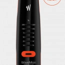
WaveMon RF-60 is a 5G-ready RF Personal Monitor (100 kHz to 60 GHz)
Wavecontrol : RF safety / EMF safety
WaveMon RF-60 Personal RF Monitor
ELECTRIC AND MAGNETIC FIELD DETECTION
Isotropic sensors with RMS response
Weighted response to international standards
ICNIRP, European Directive 2013/35/EU, FCC, Safety Code 6 (2015) and NATO
INSTANT AND AVERAGE VALUES
Alarms on instant and average values. Configurable
EXPOSIMETER WITH DATALOGGER
Data collecting and Reporting
GPS AND ALTIMETER
Geolocation of measurements
HIGH INTENSITY AUDIBLE, VISIBLE AND VIBRATORY ALARM
With user definable trigger threshold
USB COMMUNICATION PORT
Data downloading, set-up and battery charging
WaveMon_RF-60_Datasheet_EN.pdf
WEIGHTED RESPONSE
The WaveMon gives a specific weighted response for each standard. It is not just single model that attempts to follow all standards at once. Such an approach will always result in poorer accuracy. This is a weighted response, designed to follow the limits of the applicable standard, for greater accuracy.
The following monitors are now available:
WaveMon RF-60 ICN → ICNIRP version
WaveMon RF-60 EUD → European Directive 2013/35/EU version
WaveMon RF-60 FCC → FCC version
WaveMon RF-60 SC6 → Safety Code 6 (2015) version
WaveMon RF-60 NATO → NATO version
If you need a personal radio frequency monitor that specifically follows some other standard, please let us know.
DATALOGGER
The WaveMon is a radio frequency exposimeter that have a datalogger for continuous data recording.
Communication with the device is through a USB port that allows you to parametrise the device and download the recorded data. This makes it easy to create reports and allows you to keep a record of your exposure data for your safety.
PRACTICALITY
We have created an accessory that allows you to attach the personal RF monitor to your harness, arm or belt and so take it in hand to hold it near a radiation source and then put it back in place easily.
You can also secure it with a small carabiner so that it won’t be dropped.
BATTERIES
The device is small and lightweight and works with AA batteries that can be recharged via the USB port. It can also use standard AA batteries, so that they can always be easily replaced.
Easy, isn’t it? Because we want you always to be protected.
GPS AND ALTIMETER
The WaveMon is the only RF personal monitor equipped with a GPS and Altimeter for geolocation of measurements.
As an example, in a telecommunication tower, the GPS will provide the geographical position of the tower and the Altimeter the relative height from the ground. Thus, the radio frequency monitor will record 'Exposure Level' together with 'Date', 'Time', 'Geographical Position' and 'Height' on the Tower, allowing you to perfectly locate the hotspots.
ALARMS ON INSTANT AND AVERAGE VALUES
The WaveMon is the only personal RF monitor that can give alarms for average value and instantaneous value at the same time.
Remember that internationally established exposure limits are specified as values averaged over a given time (e.g. 6 or 30 minutes). Some important examples include the limits established under ICNIRP, FCC, Safety Code 6, European Directive 2013/35/EU, etc.
USER-CONFIGURABLE ALARMS
Over-exposure alarms can be configured from a PC with all their parameters. Two different alarms can be programmed and personalised separately. The following basic parameters can be personalised:
Value type (generated by instantaneous or average value)
Alarm level (% of limit)
Type of alarm (sound, vibration or both)
Low frequency immunity
Experience shows that personal RF monitors with poor immunity to low frequencies give false alarms near high-voltage lines or other types of powerful electric equipment.
The WaveMon is the personal monitor with the best immunity and it can work in electric field intensity conditions of up to 30 kV/m at 50/60 Hz without giving false readings of non-existent RF levels. That is better, for example, than the occupational exposure limit under ICNIRP: 20 kV/m.
RF ABSORTION
When the personal monitor is worn on the body, which is how it is most often used, reflections of electromagnetic fields from the body itself can affect the measurement and compromise its accuracy.
The holder for the WaveMon includes an RF absorbent material to reduce that effect. When the device is in the holder, next to the body, the absorbent material is placed strategically between the sensor and the body, but when it is used away from the body, outside the holder, that material is not present and the WaveMon gives an undisturbed isotropic behaviour.
Fully compliant with ITU-T K.145
The Recommendation ITU-T K.145, issued by the International Telecommunication Union, recommends that RF personal monitors (exposimeters) be equipped with a list of basic features in RF safety for RF workers worldwide.
The WaveMon is fully compliant with this Recommendation.
In addition, Wavecontrol is member of the National Association of Tower Erectors (NATE) in the US, organization promoting the highest standards of safety for Tower Climbers and RF Workers
MAIN CHARACTERISTICS OF THE WAVEMON
Conforms to international electromagnetic field safety standards
E-field measurements up to 60 GHz and H-field measurements up to 1 GHz
Isotropic sensors
RMS detection
Weighted response chosen from among ICNIRP, European Directive 2013/35/EU, FCC, Safety Code 6 (2015) and NATO, for direct comparison with the standard limit
Instantaneous and average values, according to international standards
High immunity at a 50/60 Hz: 30 kV/m
User-configurable alarms
High intensity audible, visible and vibration alarms
Customisable alarm threshold
Optional GPS and altimeter
Datalogger to report and record data
RF absorption to reduce reflections from the user’s body
USB for PC connection to parameterise and download data
Small and lightweight
Powered by 2 standard disposable or rechargeable (via USB port) batteries
Autonomy over 200 hours
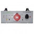
TBL5032-3 50uH Line Impedance Stabilisation Network LISN – CISPR 16
General Test Equipment
Product Description
TBL5032-3 50uH Line Impedance Stabilisation Network LISN – CISPR 16
The TBL5032-3 is a Line Impedance Stabilization Network for the measurement of line-conducted interference within the range of 9 kHz to 30MHz, according to the CISPR 16-1-2 standard. The device is designed for testing 3-phase and single phase, AC-powered equipment with supply voltages up to maximum 450V/260V and 32A. Conducted noise can be measured on each phase and on the neutral conductor. The TBL5032-3 has separate RF outputs for each phase and neutral and consequently can be coupled with the TBLM1 to split the emissions in its common mode and differential mode components. The TBL5032-3 has no integrated high pass filter at the RF outputs, but comes with an external 9 kHz coaxial high pass instead.The single-phase DUT socket is available in country-specific variants.
SPECIFICATIONS
Frequency range: 9 kHz to 30 MHz
Impedance: 50 Ω ║ (50 µH + 5 Ω)
Artificial hand: 220 pF + 511 Ω
Switchable PE: 50 Ω ║ 50 µH
250µH pre-filter
Separate RF outputs for each line and neutral
Air core inductors
Line voltage: max. 540V/260V / 50 – 60 Hz, CAT ‖
Max. current per line and neutral: 32A @ 23°C each
3-phase DUT socket: CEE/IEC60309, 3L+N+PE, 32A, female
Single-phase DUT socket: country specific
Power connector: CEE/IEC60309, 3L+N+PE, 32A, male
Measurement connectors: 50 Ω BNC
External 9 kHz high pass filter, N-male / N-female
Operating Temperature Range: +5°C … + 40°C; 5% to 80% RH
APPLICATION
EMC conducted noise measurements
Please click here for : Specifications
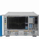
Ceyear 3672A/B/C/D/E Vector Network Analyzer
Vector Network Analyzers
Product Description
3672 Series Vector Network Analyzers include 3672A (10MHz~13.5GHz), 3672B (10MHz~26.5GHz), 3672C (10MHz~40GHz), 3672D (10MHz~50GHz) and 3672E (10MHz~67GHz). 3672 analyzers provide multiple calibration types including frequency response, single port, response isolation, enhanced response and full dual-port, electronic calibration etc., offer various display formats such as logarithmic amplitude, linear amplitude, standing-wave, phase, group delay, Smith chart and polar coordinates, etc. They are designed with several standard interfaces: USB, LAN, GPIB and VGA etc. Besides all measurement functions same as traditional vector network analyzer, through configuration of functional options, 3672 analyzers are also capable of multifunctional & comprehensive parameter test of mixer/converter, gain compression two-dimensional sweep and pulse S-parameters, as well as accuracy measurement of amplitude-frequency characteristics, phase-frequency characteristics and group delay used in the field of transmitting/receiving (T/R) module measurement, dielectric material properties measurement, microwave pulse characteristics measurement and optoelectronic properties measurement, which are indispensable instruments for scientific research and manufacturing process of radar, communication, and navigation systems.
FUNCTIONS & FEATURES
Available in multiple display formats such as logarithmic amplitude, linear amplitude, Standing-wave, phase, Smith chart
With USB, GPIB, LAN and VGA display interface
12.1-inch-high resolution touch screen
Record/run, one-click operation greatly simplifies the measurement setting steps and improves the efficiency
Available in functions as pulse S parameter measurement, time-domain measurement, mixer measurement, gain compression two-dimensional sweep measurement, THz frequency extension, antenna & RCS measurement etc.
Simple and novel operation interface
Flexible and optional calibration types, compatible with multiple calibration kits
3672 Series of Vector Network Analyzers provide multiple calibration types, including smart Cal (guided calibration), unguided calibration (using mechanical calibration kit to conduct through response calibration, through response & isolation calibration and single port calibration, enhanced response calibration as well as full two-port SOLT calibration and TRL calibration) and electronic calibration (E-Cal) etc. Users can select calibration kits, such as coaxial 3.5mm calibration kit and electronic calibration kit based on test requirements, which greatly facilitates testing on devices with different interfaces.
Multiple windows to display all measuring channels
The analyzers possess functions of multi-channel and multi-window display, support up to 64 channels. Maximum 32 measuring windows can be simultaneously displayed, and each window can simultaneously display up to 16 test traces, which improves throughput and test productivity results.
Wide dynamic range
3672 Series of Vector Network Analyzers are designed with the concept of mixer receiving, which effectively extends the dynamic range of the complete machine and meets the test demand for wide dynamic range.
Abundant peripheral interfaces, flexible and practical
Adopting the software & hardware platform consisting of embedded computer module compatible with PC and Windows operation system, 3672 Series of Vector Network Analyzers realize the perfect combination of the instrument and PC. I/O interfaces (including GPIB, USB, and LAN, etc.) are the optimum selection for data communication.
Low trace noise, high test accuracy
The excellent performance of 3672 Series Vector Network Analyzers in trace noise highly improves the accurate measurement of low insertion loss devices. (Take 3672B as an example)
Time-domain analysis
With the time-domain option, 3672 Series Vector Network Analyzers computes the inverse Fourier transform of the frequency-domain data to display reflection or transmission coefficients versus time, which can detect the discontinuous points of DUT and locate the DTF accurately.
TYPICAL APPLICATIONS
Automatic test
3672 Series Vector Network Analyzers can provide you integrated automatic test solutions to ensure high quality tests and decrease R&D costs of test significantly. Automatic test system is capable enough to help engineers accomplishing complicated tests under various complex environments.
Download User Manual Here :Click Here
Download Purchase Guide Here:Click Here
Download Fast Manual Here:Click Here
Download Programming Manual Here: Click Here
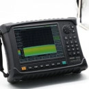
Ceyear 4024CA Handheld Spectrum Analyzer
Spectrum Analyzer
Product Description
PRODUCT OVERVIEW
The 4024CA spectrum analyzer is a broadband handheld real-time spectrum analyzer designed for field testing. The maximum real-time analysis bandwidth reaches 120MHz. It has real-time spectrum analysis, 5G NR demodulation analysis, LTE FDD/TDD demodulation analysis, GSM/ EDGE demodulation analysis, directional analysis and other measurement function modes, as well as field strength measurement, channel power, occupied bandwidth, adjacent channel power, audio demodulation, harmonic distortion, spectral emission mask/spurious emission mask, indoor/outdoor map measurement It adopts 8.4-inch large-screen LCD and capacitive touch screen integrated design to facilitate user operation. The structure adopts a handheld chassis, which is small in size, light in weight, flexible in power supply, easy to maneuver, and is extremely suitable for on-site use.
The 4024CA spectrum analyzer can be used for on-site debugging and installation and maintenance of mobile communications, wireless communications, radar, satellite communications and other equipment, wireless communication signal demodulation analysis, interference source direction finding and map positioning, broadband modulation or transient signal test analysis In other fields, it can provide a relatively complete solution for the user's external field spectrum test.
FUNCTIONS & FEATURES
Main Characteristics
l Wide frequency range: from 9kHz to 9GHz
l Full-band preamplifiers configuration
l Low displayed average noise level: -163dBm@1Hz RBW(typical)
l Excellent RF specification performance:
l Phase noise performance: -115dBc/Hz@100kHz frequency offset@1GHz carrier
l Input TOI point: +13dBm (Typical)
l Amplitude accuracy: ±1.3dB
l Real-time spectrum analysis function
l Support persistence spectrum and waterfall display mode
l Maximum real-time analysis bandwidth: 120MHz
l RTSA with 5.8us POI
l Resolution bandwidth: 1Hz~10MHz(1/3 step), 20MHz
l 512MHz IQ waveform capture
l Various measurement functions: spectrum analyzer, interference analyzer (spectrogram, RSSI), RTSA, 5G NR demodulation, LTE FDD/TDD demodulation, GSM/EDGE demodulation function etc.
l Various intelligent measurement functions: field strength measurement, channel power, occupied bandwidth, adjacent-channel power ratio, tune & listen, carrier-to-noise ratio, emission mask, indoor/outdoor map measurement, Support GPS/BEIDOU positioning and frequency taming calibration function of the crystal oscillator in the machine
l Various auxiliary test interface: 10MHz reference input/output interface, GPS antenna interface, zero span IF output interface, external triggering input interface etc.
l Easy & convenient user operation: 8.4 inch high definition LCD and large font display, convenient capacitive touch screen operation, combination of LCD and touch screen, various display modes etc.
l Working temperature range: -10℃~+50℃
l Power supplied by battery or AC
TYPICAL APPLICATIONS
Comprehensive Performance Evaluation of wireless communication base stations
4024CA spectrum analyzer has 5G NR, LTE FDD/TDD, GSM/EDGE and other wireless communication signal demodulation analysis and 120MHz bandwidth real-time spectrum analysis function, adopts a handheld structure, small size, light weight, battery-powered , Can be applied to the field installation and commissioning of wireless communication base stations and maintenance support.
Field Test and Diagnosis of Transmitter and Receiver
4024CA spectrum analyzer has various measurement function modes like spectrum analyzer, interference analyzer, Real-time spectrum analyzer, etc., as well as various intelligent measurement functions such as indoor/outdoor map measurement, channel power, occupied bandwidth, adjacent-channel power ratio, carrier-to-noise ratio, field strength measurement, emission mask etc.. It can provide comprehensive spectrum analysis and diagnosis service for the field test of transmitter and receiver.
Broadband Spectrum Monitoring, Interference Recognition
Connected with external directive antenna, 4024CA spectrum analyzer can be used for electromagnetic environment detection, radio interference analysis, electromagnetic environment background assessment, spectrum monitoring and illegal channel interference signal recognition.
Download Purchase Guide Click Here : Click Here
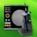
FiberView FV-3100
Optical Inspectors
Product Description
The FV-3100 (FiberView) is Lightel's benchtop digital microscope designed for inspecting and capturing images of large core fiber. The large 1400µm x 1000µm Field of View enables inspection of fibers as large as 1mm, with digital zoom available for additional detail. FiberView can also be useful for 125µm fiber when it is important to see a larger area of the connector.
Powered by the USB port of a PC, FiberView's intuitive design is simple and convenient to use. The included software can be mastered in minutes.
Easy to focus and center
Direct USB2.0 to PC connection
Powered by USB
Zoom up to 3x
Free image capture and viewing software
Include notes with image captures
FiberView (FV-3100)
Field of View
~ 1400µm x 1000µm
Resolution
0.5µm detectable
Focus
Manual adjustment range ±2mm
Axis Adjustment
Manual X & Y adjustment range ±1mm
Light source
Blue LED
Power supply
PC USB2.0 port
Dimensions
H 210mm (with tip), W 120mm, D 123mm
Weight
915g
Operating Temperature
0°C to 50°C
Storage Temperature
-20°C to 70°C
System Requirements
Windows XP, Vista, Windows 7, Windows 8
(FiberView software)
32 and 64-bit systems supported
Download specifications here : Click Here
Advantest R3561L CDMA Test Source (Refurbished)
Used and Refurbished Test Equipment
Product Description
The Advantest R3561L is a used CDMA Test Source Unit. The Advantest R3561L CDMA test source unit is used in combination with the R3465/3463 series modulation spectrum analyzer. CDMA test source control option “OPT. 09” is necessary for the R3465/3463. The R3561L outputs a modulated signal conforming to IS-95 to test the receiver characteristics of the base station. One unit can be applied to both cellular and PCS systems. The 3561L can be used to test base & mobile station for both cellular & PCS CDMA systems Used in combination with the R3465 / R3463series modulation spectrum analysis.
One unit covers a wide frequency band (for cellular and PCS)
50 MHz to 2 GHz (1 Hz resolution)
High waveform quality: 0.96
Modulated signal conforming to IS-95
Applicable to all data rates
Tracking generator function
Built-in AWGN source
Click Here to download Operation Manual
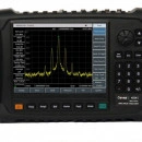
Ceyear 4024A/B/C/D/E/F/G Spectrum Analyzer
Spectrum Analyzer
Product Description
4024D/E/F/G Spectrum Analyzer possesses many advantages: a wide frequency range, high performance, high sweep speed, various functions, and easy operation. In terms of performance specifications, it has advantages of excellent displayed erage noise level, low phase noise, and high sweep speed; In terms of measurement functions, it enjoy rich measurement functions of spectrum analyzer, interference analyzer, AM/FM/PM analyzer, power meter, channel scanner etc., as well as intelligent measurement functions of channel power, occupied bandwidth, adjacent-channel power ratio, tune & listen, emission mask, and carrier-to-noise ratio etc.. 4024 deploys the integrated design of 8.4 inch LCD and capacitive touch screen, which improves the display definition and operation convenient. The series are handheld, compact and lightweight, with flexible power supply, which are very suitable for field work.
4024 can be used for signal and equipment test in the fields of aerospace, microwe & satellite communication, radio communication, radar monitoring, electronic countermeasures & reconnaissance, and precision guidance.
FUNCTIONS & FEATURES
Wide frequency range: from 9KHz to 44GHz, 4 models
Low displayed erage noise level: -163dBm@1Hz RBW(typical)
Excellent phase noise performance: -106dBc/Hz@100KHz frequency offset@1GHz carrier
High sweep speed: for 1GHz span, shortest sweep time <20ms
Resolution bandwidth: 1Hz~10MHz
Full-band pre-amplifier: standard configuration
Rich measurement functions: spectrum analyzer, interference analyzer (spectrogram, RSSI), AM/FM/PM analyzer, channel scanner, high accuracy power meter etc
Various intelligent measurement functions: field strength measurement, channel power, occupied bandwidth, adjacent-channel power ratio, tune & listen, carrier-to-noise ratio, emission mask
Various auxiliary test interface: 10MHz reference input/output interface, GPS antenna interface, zero span IF output interface, external triggering input interface etc
Easy & convenient user operation: 8.4 inch high definition LCD and large font display, convenient capacitive touch screen operation, combination of LCD and touch screen and various display modes, etc
Operating temperature range: -10℃~50℃. Power supplied by battery or adapter
Various measurement functions
Interference analyzer (spectrogram)
AM/FM/PM demodulation
Channel scanner
Power meter (USB power probe)
Comprehensive intelligent measurement function
Field strength measurement
Channel power
Occupied bandwidth
Adjacent-channel power ratio
Emission mask
Carrier-to-noise ratio
Limit line
List sweep
Multi-traces
Various auxiliary test interfaces
Easy & convenient user operation
One-click quick measurement
Storage and invocation of state and data
Combination of 8.4 inch LCD and capacitive touch screen, smaller light refraction and clearer display
Convenient capacitive touch screen operation
Various display modes, better experience under outdoor light and night vision
Backlit keys enables easy viewing in darkness
Outdoor mode
Night vision mode
TYPICAL APPLICATIONS
Comprehensive performance evaluation of electronic weapon equipment
4024 series he advantages of a wide frequency range, high performance specifications, a high sweep speed, multiple test functions, and easy operation. They are handheld, compact and lightweight, which can be powered up by a built-in battery. The series can be used for the field installation & calibration, repair & maintenance of electronic weapon equipment in fields of radar, communication, electronic countermeasures & reconnaissance, and precision guidance etc.
Field test and diagnosis of transmitter and receiver
4024 series he rich measurement function modes like spectrum analyzer, interference analyzer, AM/FM/PM analyzer, power meter, channel scanner etc., as well as various intelligent measurement functions such as channel power, occupied bandwidth, adjacent-channel power ratio, carrier-to-noise ratio, field strength measurement, emission mask etc.. They can provide comprehensive spectrum analysis and diagnosis service for the field test of transmitter and receiver.
Broadband spectrum monitoring, interference recognition
Connected with external directive antenna, 4024 series can be used for electromagnetic environment detection, radio interference analysis, electromagnetic environment background assessment, spectrum monitoring and illegal channel interference signal recognition.
Downloads:
Download user manual Click Here :User Manual
Download Purchase Guide Click Here : Purchase Guide
Download Fast Manual Click Here : Fast Manual
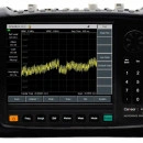
Ceyear 4957D/E/F Microwave Analyzer
RF & Microwave
Product Description
The 4957D/E/F microwave analyzer has a frequency range of up to 18 GHz/26.5 GHz/40 GHz, and is provided with various functions, including dual port vector network analysis, cable and antenna analysis, vector voltage measurement, spectrum analysis (channel power, adjacent channel power, occupied bandwidth, interference analysis and frequency counting), field strength measurement and power measurement, providing users with powerful comprehensive analysis capabilities.
Dual-port vector network analysis has the capability of fast and accurate measurement of RF network parameters, provides logarithm, linearity, phase, group delay, impedance circle diagram, polar coordinates, standing wave ratio and other displaying formats and also provides time domain measurements option.
The cable and antenna analysis can measure the standing wave ratio, return loss, impedance, cable loss and other parameters of the microwave network such as antenna, transmission line and cable. In addition, the Distance-To-Fault (DTF) function enables to conveniently measure the impedance discontinuous point of the cable antenna feeder and cable.
The vector voltage measurement function replaces the traditional vector voltmeter with an integrated solution that accurately analyzes the electrical length of cables and other devices under analysis.
The spectrum analyzer is a standard function spectrum analyzer that comprehensively measures the spectral features of the electromagnetic environment.
The field strength measurement function features user-friendly interface and high analysis sensitivity, can effectively monitor the electromagnetic spectrum with the corresponding analysis antenna and is widely used in space electromagnetic environment monitoring and radio management.
The USB power sensor is configured to achieve large dynamic range and high-precision power measurement, or implement power monitoring through the spectrum input port.
FUNCTIONS & FEATURES
Main Features
l Rich analysis functions: Cable and antenna analysis, vector network analysis, spectrum analysis, field strength measurement, power monitoring, vector voltage measurement and USB power measurement, etc
l Compacted size, light weight, secondary environment adaptability, easy to carry and suitable for special occasion analysis
l 8.4-inch LCD touch screen features easy to operate, friendly man-machine interface and intuitive display result
l Analysis data can be stored and recalled, providing three storage media: 1.5G or more large-capacity internal memory, USB external memory and SD external memory
l Battery-powered, suitable for field use, power management intelligence, providing remaining battery indicator and low battery alarm function and sleep energy saving function
l Providing six independent marker display functions, with marker position displayed when swiping with finger
l Providing data storage, playback and comparison capabilities
l Providing USB, LAN and other interfaces for program control and data transmission
TYPICAL APPLICATIONS
Network Analysis
The 4957D/E/F microwave analyzer has the network analysis frequency range of 30kHz~18GHz/26.5GHz, 50MHz~40GHz, provides standard full 4S parameter vector network analysis and measurement capability and can carry out fully S-parameter analysis against amplifier, filter, attenuator and duplexer, and its display format includes logarithm, linearity, phase, group delay, impedance, polar coordinates, standing wave ratio, etc.
Spectrum Analysis
The 4957D/E/F microwave analyzer has the spectrum analysis function (spectral analysis, channel power, occupied bandwidth, adjacent channel power ratio, and frequency counting) and has a frequency range of 100kHz~18GHz/26.5GHz/40GHz, featuring with wide frequency bandwidth, high sensitivity, high dynamic range and good phase noise and has the capability of implementing fast and efficient signal detection and measurement. In addition, this analyzer can display 3 traces at the same time, and has provided different detector mode selections such as standard, sampling, positive peak, negative peak and average. What’s more, it has provided interference analysis, spectrogram, waterfall, data recording and playback.
Cable and antenna analysis (Optional)
As a cable and antenna analyzer, the 4957D/E/F microwave analyzer can measure the return loss, voltage standing wave ratio, impedance, cable loss, and fault point distance of the analyzed components such as cables and antennas, and return loss and Distance-To-Fault measurement will help user determine the specific cause of the fault in the cable and antenna system that degrades the overall system. What’s more, it has provided built-in common cable and antenna feeder parameters for easy use.
Vector Voltage Measurement (Optional)
The 4957D/E/F microwave analyzer has the vector voltage measurement frequency range of 30kHz~18GHz/26.5GHz, 50MHz~26.5GHz, which can accurately match and measure the electrical length and phase shift of the device under analysis, and can perform reflection and transmission analysis.
USB Power Measurement (Optional)
The 4957D/E/F microwave analyzer can perform power measurement by selecting the CETC 872XX series USB continuous wave power sensor, which can analyze the RF/microwave power up to 40GHz.
Power Monitoring (Optional)
The 4957D/E/F microwave analyzer can also be used for power monitoring measurements through the spectrum input port, and has a frequency range of 100kHz to 18GHz/26.5GHz/40GHz.
Field Strength Measurement (Optional)
The 4957D/E/F microwave analyzer can also be used for field strength measurement with the corresponding analysis antennas (such as CETGC's 89101A/B/C/D, etc.), which is widely used in space electromagnetic environment monitoring and radio management. It supports user antennas, allowing users to customize their own antennas.
Supporting List Sweep
In addition to frequency sweep, including spectrum analysis, cable and antenna analysis, network analysis, etc., it also supports list scanning mode and makes the parameters in each segment become independent of each other.
Supporting Upper and Lower Limit Lines
Spectrum analysis, cable and antenna analysis, and network analysis support limit line analysis. The limit line can be used as a visual reference or as a basis for PASS/FAIL judgment. If the analysis data exceeds the upper limit line or is lower than the lower limit line, the speaker will send a "beep" sound to remind the user that the data is out of tolerance.
Menu in Both Chinese and English for Easy Operation
Both Chinese and English menus are available in the machine, which is very convenient to switch with one button.
Sleep and Energy Saving Function
It provides the function of displaying sleep for energy saving, set the sleep time, and when the sleep function is turned on and is not operated for a certain period of time, it will automatically turn off the display or shut down, thus saving energy, and effectively extending working time and life of battery.
More Markers
It provides up to 8 independent markers to display the parameters of the marker position, as well as provide maximum, minimum or peak search. Each marker provides a △ mode to make analysis readings become easier. In addition, the ruler on the left side of the display facilitates the judgment of the analysis results.
Automatic Software Upgrade through U Disk
The 4957D/E/F microwave analyzer provides a USB interface that can be used for software intelligent upgrade and data backup. User can conveniently use the USB flash drive to upgrade and maintain the instrument, which only takes a few steps to operate and is simple and quick. The instrument should be restarted after the upgrade.
Typical Applications
The 4957D/E/F microwave analyzer is characterized by compact size, light in weight, easy to carry, numerous analysis parameters and comprehensive analysis functions. What’s more, it is very suitable for multi-parameter analysis requirements and is battery-powered, serves as a powerful tool for routine maintenance and repair of field engineering installation and debugging of various microwave electronic equipment. In addition, it is widely used in radar, communications, radio and television, radio management and other fields. Besides, it is also an optimized choice for college teaching.
Main Performance Parameter Analysis of Radar
As a full-featured analyzer, the 4957D/E/F microwave analyzer can perform the main performance parameter analysis of subsystems in respect of radar antenna, transmitting and receiving of up to 18GHz/26.5GHz/40GHz, including the standing wave ratio, reflection factor, insertion loss, return loss and impedance characteristics etc. of antenna subsystem, frequency of the transmitted signal, spectral characteristics etc. of transmitting subsystem, center frequency, gain, loss, bandwidth, dynamic range of receiving subsystem.
Multi-Parameter Analysis in the Fields of Cable TV and Wireless Communication Etc
Cable TV, cellular telephone systems, digital mobile communication operators and equipment manufacturers use the 4957D/E/F microwave analyzer to carry out on-site comprehensive analysis of spectrum distribution, antenna contact performance, S-parameters of feed components and feed-through power.
Downloads:
Download user manual Click Here : User Manual
Download Purchase Guide Click Here : Purchase Guide
Download Fast Manual Click Here : Fast Manual
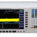
Ceyear 4051A/B/C/D/E/F/G/H/L Signal/Spectrum Analyzer
Signal Generators
Product Description
Equivalent to Keysight R&S
4051 series signal/spectrum analyzer have excellent performance in dynamic range, phase noise, amplitude accuracy, and measurement speed. 4051 series have various measurement functions including high-sensitivity spectrum Analyzer, standard power measurement components, IQ Analyzer, Vector Signal Analyzer, Real-Time Spectrum Analyzer, Transient Analyzer, Pulse Signal Analyzer, Audio Analyzer, Analog Demodulation measurement, and Phase Noise measurement, Noise Figure, etc., which can provide you reliable high-performance measurement service. 4051 series have good extension capacity. Its performance can be further improved by flexible configuration of different options. Through various digital and analog signal output interfaces, the spectrum analyzer can be taken to establish measurement systems or get secondary development. It can be widely used for signal and equipment measurement in field of aviation, aerospace, radar detection, communication, electronic countermeasures, and navigation etc..
FUNCTIONS & FEATURES
● Coaxial frequency range up to 67GHz
● Max. 550MHz analysis bandwidth
● Excellent measurement & receiving performance
● Comprehensive spectrum analysis capability
● Abundant measurement application functions
● Powerful RF signal streaming and playback analysis function
● Flexible analog signal output interface
Wide Frequency Range
9 optional frequency band configuration, 3Hz ~ 4/9/13.2/18/26.5/40/45/50/67GHz
The frequency can be extended up to 500GHz (with external frequency extension options)
Maximum 550MHz Analysis Bandwidth
Provide 4 analysis bandwidth configuration: 10MHz (standard), 40MHz, 200MHz, 550MHz etc.
The bandwidth can be flexibly selected from 10Hz to 550MHz, more than 40 choices.
4GB storage depth, according to the selected bandwidth, the seamless capture time differs from 1.25s to several hours.
Excellent Measurement & Receiving Performance
Wideband preamplifiers (up to 50 GHz) can be configured for the host frequency band
1GHz measurement DANL is -156dBm/Hz; the typical value is -167dBm/Hz with preamplifier
50GHz measurement DANL is -141dBm/Hz; the typical value is -150dBm/Hz with preamplifier
67GHz measurement DANL is -135dBm/Hz
Full digital IF design, excellent scale fidelity and IF error
Comprehensive Spectrum Analysis Capability
Support frequency sweep and FFT sweep.
Zero frequency band fast sweep, the fastest sweep time is 1µs
Accurate frequency counting, counting resolution can be 0.001Hz
Sweep point number can be arbitrarily selected among 101~30001
Can be configured with 6 traces, have abundant marker operation functions
6 trace detector modes, 3 average types
Time gate measurement function
Occupied bandwidth, channel power, adjacent channel power measurement functions
Measurement functions of power statistics, burst power, harmonic distortion, TOI, spurious emission etc.
Transient Analysis and Signal Playback Analysis
Frequency-domain and time-domain correlation measurement is helpful for understanding and deeply analyzing transient signal events
Waterfall diagram display, analyzing the macroscopic law of analysis signal spectrum changing versus time
Simultaneously analyze the changes of analysis signal frequency, amplitude, and phase versus time, to assist the measurement in the process of power control and frequency locking
Support 500M samples (64 bits accuracy) seamless capture data storage
Support multiple storage formats of signal files: CSV, DAT, etc.
Support the playback analysis of signal files
Vector Signal Analysis Function
With comprehensive time domain, frequency domain, modulation domain signal analysis and viewing function, it supports more than 20 modulation and demodulation modes.
Real-time Spectrum Analysis Function
4051 can achieve seamless Real-time Spectrum Analysis, and frequency template trigger function, which can be used to trigger, capture, and analyze complex signals.
Max. real-time analysis bandwidth: 40MHz, 200MHz(optional), frequency coverage 67GHzDigital phosphor spectrum,seamless waterfall, instantaneous spectrum, power vs. time, frequency vs. time and other charts100% POI, Min. duration of the signal: 4.3μs
Pulse Signal Analysis Function
Pulse signal spectrum and time domain characteristic measurement supports more than 20 kinds of pulse parameters measurement (including time, amplitude, frequency and phase).
Can perform detailed analysis of amplitude, intrapulse frequency/phase characteristics, and spectral characteristics of arbitrary pulse
Pulse trend statistics for arbitrary pulse parameters
Phase Noise measurement / Audio Analysis /—Analog Demodulation Analysis function
The Phase Noise measurement relies on the excellent phase noise of the signal analyzer and provides one-button automatic measurement to meet the daily signal source phase noise measurement applications.
Independently optimized audio measurement channel for low frequency signal parameter measurement and analysis
Analog Demodulation Analyzer is used to simulate terminal, radio, and general analog modulation source measurement. Demodulate the AM/FM/ΦM signal and measure parameters such as modulation index, modulation distortion, residual FM, and FM linearity and so on.
Powerful RF Signal Streaming and Playback Analysis Function
Bandwidth of broadband real-time signal recording up to 200MHz
Data recorder, both SSD and HDD can be selected
Flexible Analog Signal Output Interfaces
275MHz~475MHz high intermediate frequency output, 1 Hz frequency steps.
10MHz~160MHz IF output, 1Hz frequency steps, 4-gear automatic gain control level
Digital reconstruction signal output, provide IF, AM/FM demodulation and IQ demodulation signal output
New Operating Experience
Humanized automatic tuning and automatic scale
One-button measurement
10.1-inch LCD with 1280*800 high resolution
TYPICAL APPLICATIONS
Comprehensive assessment for the performance of electronic system
4051 can be widely used for the comprehensive assessment for the performance of electronic systems in fields of radar and communication etc., which provides high-sensitivity, wide dynamic range, high-precision and high-efficiency solutions.
Measurement and diagnosis of transmitter and receiver
With the functions of spectrum analysis, one-button measurement and instantaneous analysis, Analog Demodulation Analyzer as well as Pulse Signal Analyzer, Phase Noise Measurement, and etc., 4051 can provide comprehensive diagnosis service for transmitter and receiver measurement.
Directly used for the integration of ATE, and provide signal output, data output and result analysis for the system.
The application of electromagnetic signal RF streaming: it can be applied to data acquisition and recording in the process of large-scale weapon test and space electromagnetic spectrum environment.
Downloads:
Download user manual Click Here :User Manual
Download Purchase Guide Click Here : Purhcase Guide
Download Fast Manual Click Here :Fast Manual
Ceyear 1465A/B/C/D/F/H/L-V Vector Signal Generator
Signal Generators
Product Description
1465-V series signal generators has excellent vector modulation performance within the frequency range of 100kHz-67GHz. It has 200MHz internal modulation bandwidth and 2GHz external modulation real-time bandwidth, which can meet various modulation needs of wideband signals. The generator has excellent spectrum purity and output power specifications. The phase noise of 10GHz carrier @10kHz frequency offset can be reached to -126dBc/Hz, to meet high-level test needs which have strict requirements of testing signals. The generator also has excellent vector modulation accuracy and at the full frequency range the EVM is less than 1.4%(4Msps), which makes the generator be used in metrology purpose. The baseband signal generator can be set easily with flexible performance and many modulation formats. More than 20 kinds of common modulation formats are supported, such as PSK, QAM, FSK, ASK and so on.
FUNCTIONS & FEATURES
Main Characteristics
Broadband vector signal generatiLarge vector modulation bandwidth
High purity spectrum
Broadband and high-power output
Metrology grade vector modulation accuracy
Complete universal digital modulation format
Convenient touch screen control
Multiple control and function extension interfaces
Broadband vector signal generation
1465-V series signal generators can provide various signal testing solutions covering 3GHz/6GHz/10GHz/20GHz/40GHz/50GHz/67GHz to meet user’s specific needs in different fields. Especially, 1465L-V signal generator with 100kHz~67GHz frequency range can meet test needs of most users.
Vector Modulation Bandwidth
1465-V series signal generators can provide 200MHz internal modulation bandwidth and 2GHz external modulation bandwidth(above 3.2GHz carrier)vector signal generation function.
Arbitrary Wave Data Format Download
1465-V series signal generators support direct download and display of arbitrary waveforms. The file formats include Mat-File 5, ASCII, Binary, cap and csv. The generator has a 2GSa storage depth.
High Purity Spectrum
1465-V series signal generators are able to output extremely pure signal spectrum. The single side band phase noise of 10GHz carrier and 10kHz frequency offset has a typical value of -126dBc/Hz and 1GHz carrier and 10kHz frequency offset typically reaches -142dBc/Hz. It can be used for Doppler radar as well as high-performance receiver block and adjacent channel selectivity test. It also can be an ideal alternative device for local oscillator and low jitter timer.
Broadband and High-power Output
For high-power option H05, typical values for the maximum output power are +22dBm at 20GHz and +16dBm at 40GHz.There’s no need for an external amplifier when you need high power stimulus signal during test. And what’s more, the power accuracy and stability are better.
Metrology Grade Vector Modulation Accuracy
1465-V series signal generators has excellent vector modulation accuracy. The EVM is less than 1.4% (typical value<1.0%) at the frequency range 100kHz-40GHz, and EVM<2.5% (typical value<1.5%) at the frequency range 40GHz-67GHz.
Complete Universal Digital Modulation Format
1465-V series signal generators can provide real-time generation of universal digital modulation signals, including more than 20 kinds of modulations, such as PSK、QAM、FSK、MSK etc.
Convenient Touch Screen Control
A 10.1-inch LED display screen of 1280×800 resolution shows the instrument states information clearly. Conspicuous color matching, proper function division and various function panel buttons provide a fresh sight of vision, easy operation and higher test efficiency for you. Besides with the panel buttons, the instrument can be controlled independently by operating with enter knob, sliding or clicking on the touch screen, and using external keyboard or mouse.
Multiple Control and Function Extension Interfaces
Support various auxiliary interfaces such as USB, LAN, GPIB, Monitor. The USB interface can be used for data transmission and external keyboard/mouse. LAN and GPIB can be used for programmable control. The monitor connector can be used for external display when using a CRT or LCD.
TYPICAL APPLICATIONS
Communication system Test
1465-V series signal generator can generate high-performance user-defined modulation and basic digital modulation signal within frequency range of 100kHz~67GHz. The instrument can provide repeatable and reliable test signals for satellite communication. Its external wide bandwidth vector modulation and user-defined data features as well as additive noise function can create a real-world signal and help users to make product performance confirmation.
To Simulate Various Application Scenes for Radar and EM Environment
1465-V series signal generator has wide frequency range and high resolution(16bit)as well as powerful signal simulation function. It can generate complex sequences of various modulation formats by editing waveform segment under different scenes. Together with abundant functional synchronous trigger interface, it can simulate complex interference signal under actual environment and accomplish anti-interference test of radar equipment.
Provide Arbitrary Wave Modulation Signal
1465-V series signal generator has 2G sampling point waveform storage capacity. This feature can allow designer to generate a long-time test data, which may be more close to the reality. User can create one of the kinds of arbitrary wave data using the third party tools or software.
Receiver Test
1465-V series signal generator has a 140dB output dynamic range and extremely high frequency stability as well as 0.001Hz frequency resolution. It can output high-accuracy standard test signal which can solve parameter test problem such as sensitivity, dynamic range and channel selectivity to accomplish test of high-performance receiver used in radar, electronic warfare and communication equipment.
Local Oscillator Substitution
1465-V series signal generator has extremely high signal quality, thus can be used as an ideal device to substitute LO when testing transmitter and receiver and other systems. It will guarantee your test accuracy and creditability by avoiding negative influences that low-quality LO brings in.
Downloads:
Download user manual Click Here : User Manual
Download Purchase Guide Click Here : Purchase Guide
Download Fast Manual Click Here : Fast Manual
TBSCP1-10M500 RF surface current monitoring probe
Tekbox Amplifiers
Product Description
The TBSCP1-10M500 is a RF surface current monitoring probe, expanding the Tekbox product range of affordable EMC pre-compliance test equipment.The probe has a very flat response from 10MHz to 500 MHz and is characterized over the frequency range from 9 kHz to 600 MHz. The TBSCP1-10M500 is for RF current monitoring applications that need to measure RF currents flowing on surfaces such as PCB groundplanes or traces, metal planes or wires.The footprint of the RF current monitoring probe measures 40 mm x 15 mm. The transfer impedance is -5 dB Ohm with a typical 3dB bandwidth from 10 MHz to 500 MHz.
SPECIFICATIONS
Characterized frequency range: 30 kHz to 600 MHz
Transfer impedance: -5 dB Ohm with a 3 dB bandwidth from 10 MHz to 500 MHz
Suppression of orthogonal field: typ. > 15 dB avg. up to 100 MHz
Footprint: 40 mm x 15 mm
Height: 30 mm
Weight: 25 g
Connector type: SMA female
Max. primary current (DC – 400 Hz): 150 A
Max. primary current (RF): 12 A
Max. core temperature: 125 °C
Documentation Download:
TBSCP1-10M500 user manual
TBSCP1-5M300 RF surface current monitoring probe
Tekbox Amplifiers
Product Description
The TBSCP1-5M300 is a RF surface current monitoring probe, expanding the Tekbox product range of affordable EMC pre-compliance test equipment.The probe has a very flat response from 5 MHz to 300 MHz and is characterized over the frequency range from 30 kHz to 400 MHz. The TBSCP1-5M300 is for RF current monitoring applications that need to measure RF currents flowing on surfaces such as PCB groundplanes or traces, metal planes or wires.The footprint of the RF current monitoring probe measures 40 mm x 15 mm. The transfer impedance is -7 dB Ohm with a typical 3dB bandwidth from 5 MHz to 300 MHz.
SPECIFICATIONS
Characterized frequency range: 30 kHz to 400 MHz
Transfer impedance: -7 dB Ohm with a 3 dB bandwidth from 5 MHz to 300 MHz
Suppression of orthogonal field: typ. > 15 dB avg. up to 100 MHz
Footprint: 40 mm x 15 mm
Height: 30 mm
Weight: 25 g
Connector type: SMA female
Max. primary current (DC – 400 Hz): 150 A
Max. primary current (RF): 12 A
Max. core temperature: 125 °C
Documentation Download :
TBSCP1-5M300 user manual
UNI-T UTD2052CL+ (50MHz, 2CH)
Uni-Trend
Product Description
UTD2000CL+ SERIES
The UTD2000CL+ Series is a market-proven economical digital oscilloscope. This series of digital oscilloscopes has excellent technical indicators and can meet the main needs of basic testing. The front panel design is clear and intuitive,fully in line with the traditional instrument usage habits, and is convenient for users to operate
Specifications
Channels: 2
Bandwidth: 50MHz(upgraded 100Mhz)
Sampling rate: 500MS/s
Rise time: ≤7ns
Waveform capture rate: >5,000wfms/s
Memory depth: 64kpts
Trigger types: Edge, pulse, alternate, slope, video
Auto measurements: 34 parameters in total
LCD: 7 inches TFL LCD
Please Click Here for Datasheet :Data Sheet
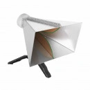
TBMA4 Double Ridged Horn Antenna
TEKBOX ANTENNAS
Product Description
CISPR 16 divides the frequency range into several bands and defines specific antennas for each of these bands. For the frequency range above 1 GHz, CISPR 16 specifies using wideband horn antennas for radiated noise measurements.
Standard wideband horn antennas for EMC applications are quite costly and cover a frequency range far wider than available on typical low cost EMC pre-compliance spectrum analyzers. In order to provide an antenna optimized for pre-compliance EMC testing applications above 1 GHz, Tekbox designed the TBMA4 double ridged horn measurement antenna.With its moderate price, it is an affordable product for radiated noise EMC precompliance testing and generating defined field strengths.
The TBMA4 is characterized from 1 GHz to 8 GHz and has a directional pattern typical for double ridged horn antennas.
The TBMA4 is a small double ridged horn antenna, with its radiating element made from edge plated PCB substrate. The housing is made from stainless steel. It is equipped with a standard female N-connector and comes together with a “pistol-grip” tripod. A standard ¼” thread on the bottom of the antenna makes it easy to connect it to most standard tripods.
Additionally, the antenna is equipped with an indexed mounting plate on its rear. The mounting plate has a 6mm threaded hole in its centre and radially positioned 4mm threaded holes in 45° steps, typical for most horn antennas.
SPECIFICATIONS
Type: double ridged horn
Frequency range: 1 GHz – 8 GHz
Nominal impedance: 50 Ω
Connector: N type female
Maximum continuous input RF power: 100 W
Isotropic gain: 6 … 14 dBi
Antenna factor: 24 … 43 dB/m
Front to back ratio: avg. 20 dB
Voltage Standing Wave Ratio (VSWR): < 3:1 over the entire frequency range; < 2:1 average
Width: 241 mm (9.49 “)
Height: 153 mm (6.03 “)
Depth: 214 mm (8.44 “)
Weight: 1.4 kg (3.08 lbs)
Tripod Adapter Thread Size: ¼”
Indexed rear mounting flange
Documentation Download:
TBMA4 Manual
TBMA4 Testreport
TBMA4 antenna factor file for EMCview
Application note: How to correctly use spectrum analyzers for EMC pre-compliance tests
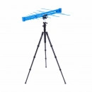
TBMA3 Log Periodic Measurement Antenna
TEKBOX ANTENNAS
Product Description
The TBMA3 is an affordable logarithmic periodic measurement antenna, targeting radiated noise EMC pre- compliance testing.
The TBMA3 is characterized from 250 MHz to 1.3 GHz and has VSWR and antenna factor values typical for log-periodic measurement antennas.
CISPR 16 divides the frequency range into several bands and defines specific antennas for each of these bands. For the frequency range above 300 MHz up to 1 GHz, CISPR 16 specifies using logarithmic periodic antennas (log-periodic antennas ) for radiated noise measurements.
The TBMA3 is an average sized log-periodic antenna, with its radiating elements and supporting booms made from powder coated aluminum alloy. It is equipped with a standard female N-connector and comes together with an antenna bracket and a mounting adapter. A standard ¼” thread on the bottom of the mounting adapter makes it easy to connect it to most standard tripods.
The TBMDA3 is shipped in a robust carrying case, as pictured above.
SPECIFICATIONS
Type: logarithmic periodic
Frequency range: 250 MHz– 1300 MHz
Nominal impedance: 50 Ω
Connector: N type female
Maximum continuous input RF power: 100 W
Isotropic gain: 6 dBi ± 1.5 dB
Antenna factor: 14.2 … 27.5 dB/m
Voltage Standing Wave Ratio (VSWR): < 1.95:1 over the entire
frequency range ; 1.35:1 average
Width: 749 mm (29.49”)
Height (With the mounting adapter): 170.23 mm (6.70”)
Height (Without the mounting adapter): 79.5 mm (3.13”)
Depth: 863 mm (33.98”)
Weight: 1.78 kg (3.92 lbs)
Tripod Adapter Thread Size: ¼”
Documentation Download:
TBMA3 Manual
TBMA3 Testreport
TBMA3 antenna factor file for EMCview
Application note: How to correctly use spectrum analyzers for EMC pre-compliance tests
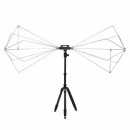
TBMA2 Biconical Antenna
TEKBOX ANTENNAS
Product Description
The TBMA2 is a biconical measurement antenna for EMC radiated emission testing and generating defined field strength. With its affordable price it is an excellent choice for any lab carrying out in house pre-compliance testing.
It is characterized from 30 MHz to 300 MHz and has a directional pattern similar to a dipole antenna.
The TBMA2 comes with a POM bracket with a ¼ ” thread insert for mounting the antenna on standard tripods.
The TBMA2 radiating elements are made of stainless steel parts to avoid the disadvantages of contact degeneration over time, which are associated with non-welded designs using aluminum. The radiating elements are not welded but fastened with grub screws, which makes assembly / disassembly simple and makes the antenna easily storable and transportable.
The antenna elements are fed via a 1:4 balun with 100 W power handling capability.
SPECIFICATIONS
Type: passive biconical
Frequency range: 30 MHz– 300 MHz
Nominal impedance: 50 Ω
Balun: 1:4
Maximum continuous input RF power: 100 W
Connector: N type female
Isotropic Gain: -12.51 to 0.55, see Figure 2 and Table 1
Antenna Factor: 10.8 to 26.3, see Figure 3 and Table 1
Voltage Standing Wave Ratio (VSWR): 1.05 to 38.05, see Figure 4 and Figure 5
Test standards: FCC, CISPR, SAE, RTCA-DO-160, Mil STD-461, etc.
Length: 138.7 cm (54.6 “) tip
Diameter: 54.2 cm (21.3 “)
Depth: 80.3 cm (31.6 “) including balun
Weight of one radiating element: 1.28 kg (2.82 lbs)
Weight of holder/balun: 0.96 kg (2.12 lbs)
Documentation Download :
TBMA2 Manual
TBMA2 Testreport
TBMA2 antenna factor file for EMCview
Application note: How to correctly use spectrum analyzers for EMC pre-compliance tests
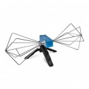
TBMA1 Biconical Antenna
TEKBOX ANTENNAS
Product Description
The TBMA1 is a small, lightweight, wideband biconical measurement antenna. With its moderate price, it is ideal for radiated noise EMC pre-compliance testing and for generating defined field strength.
It is characterized from 30 MHz to 1 GHz and has a directional pattern similar to a dipole.
The TBMA1 comes in a solid beech wood case, together with a “pistol-grip” tripod. A standard ¼” thread makes it easy to connect it to most standard tripods.
The elements are corrosion resistant and constructively locked against rotation. They are fed via a wideband balun with 2 W power handling capability. Furthermore they are protected against build-up of static charge.
SPECIFICATIONS
Type: passive biconical
Frequency range: 30 MHz – 1000MHz
Nominal impedance: 50 Ω
Maximum continuous input RF power: 2 W
Connector: N type female
Isotropic gain: -42.15 … 1.78 dBi
Antenna factor: 16.30 … 41.91 dB/m
Voltage Standing Wave Ratio (VSWR) Max < 2.8
Length: 430 mm (17 “) tip-to-tip
Diameter: 160 mm (6.3 “)
Depth: 163 mm (6.4 “) including housing
Weight: 0.46 kg (1.01 lbs)
Tripod Adapter Thread Size: ¼”
LINKS AND REVIEWS
EDN Review (EMC Blog from Kenneth Wyatt)
Documentation Download:
TBMA1 Manual
TBMA1 antenna factor file for EMCview
Application note: How to correctly use spectrum analyzers for EMC pre-compliance tests
TBLPA1 Linear Wideband RF Power Amplifier
Tekbox Amplifiers
Product Description
The TBLPA1 linear wideband power amplifier is a general purpose RF amplifier for test and measurement applications. It has an output power capability of up to 1W and can be used in the frequency range from 10 MHz to 1 GHz and with reduced output power capability even beyond.
SPECIFICATIONS
Input / Output: 50 Ohm, N femaleSupply Voltage range: 110 V…240 VSupply power consumption: 15 WOperating temperature range: -20°C to 60°CFrequency range: 50 MHz – 1 GHz, (3MHz – 1.3GHz with reduced output power capability)Gain: 36dB typ., see table 1 for details1dB output compression point @ 10MHz: +29.5 dBm typ.1dB output compression point @ 100 MHz: +30.9 dBm typ.1dB output compression point @ 500 MHz: +31.3 dBm typ.1dB output compression point @ 1 GHz: +28.7 dBm typ.Noise figure: 2.5 dB typ.2nd harmonic, 50MHz, Pout=30dBm: < – 50 dBc typ2nd harmonic, 200MHz, Pout=30dBm: < – 40 dBc typ3rd harmonic, 50MHz, Pout=30dBm: < – 30 dBc typ3rd harmonic, 200MHz, Pout=30dBm: < – 25 dBc typTotal harmonic distortion: 0.85% @200MHz, Pout=27dBm typ.1.13% @200MHz, Pout=28dBm typ.2.33% @200MHz, Pout=29dBm typ.5.6% @200MHz, Pout=30dBm typ.Third order intercept point:+50dBm, @200MHz, ∆ f = 200kHz typ.Input return loss: 50 MHz: 11dB typ.800 MHz: 16dB typ.Output VSWR:50 MHz: 2.1:1800 MHz: 1.4:1Maximum ratings:Maximum input power: +3 dBmThe output of the TBLPA1 is quite tolerant to output mismatch, however open or shorted load is not recommended, potentially can cause damage.
Small Signal Gain (measured with Pin = – 20 dBm):
3 MHz
5 MHz
10 MHz
25 MHz
50 MHz
100 MHz
200 MHz
300 MHz
400 MHz
16 dB
34 dB
43 dB
42 dB
41 dB
40 dB
39 dB
38.5 dB
38.3 dB
500 MHz
600 MHz
700 MHz
800 MHz
900 MHz
1 GHz
1.1 GHz
1.2 GHz
1.3 GHz
38 dB
37.8 dB
37 dB
35.4 dB
36.5 dB
36.2 dB
35.5 dB
33.7 dB
32.1 dB
APPLICATION
general purpose power amplifier
Documentation Downloads:
TBLPA1 manual
Application note: How to correctly use spectrum analyzers for EMC pre-compliance tests
TBMDA4B Modulated Power Amplifier
Tekbox Amplifiers
Product Description
The TBMDA4B modulated wideband power amplifier is designed in order to create an inexpensive signal source for immunity testing of electronic building blocks and products. It is designed to be driven by the tracking generator output of spectrum analyzers. With an input power range of -20 dBm…-10 dBm, it can boost the output power of a tracking generator up to 5W. With a frequency range from 100 kHz to 75 MHz, it is an ideal complement to the TBMDA3, which covers 10 MHz to 1 GHz.
The TBMDA4B is ideal to drive Tekbox near field probes in order to find the sensitive spot of an electronic circuit or to create electric fields up to 550V/m when driving the Tekbox TEM Cell TBTC0, 300V/m when driving the TBTC1, 150V/m when driving the TBTC2 or 100V/m when driving the TBTC3. Test signals for immunity testing can be CW, AM or PM modulated. Consequently, the TBMDA4B provides built in modulation capability to generate 1 kHz AM or PM signals. In PM mode, the TBMDA4B can also generate a 217 Hz Signal with 12.5% duty cycle in order to simulate mobile phone TDMA noise.
FEATURES
CW amplifier (modulation off)
1 kHz, 80% AM modulation
1 kHz, 50% duty cycle pulse modulation
217 Hz, 12.5% duty cycle pulse modulation
SPECIFICATIONS
Input / Output: 50 Ohm, N femaleSupply Voltage range: 110 V…240 VSupply power consumption: 20 WOperating temperature range: -20°C to 50°CFrequency range: 100 kHz – 75 MHzSaturated output power @ 100 kHz / Pin = -10 dBm: 36.6 dBm (4.6W) typ.Saturated output power @ 1 MHz / Pin = -10 dBm: 37.6 dBm (5.8W) typ.Saturated output power @ 10 MHz / Pin = -10 dBm: 37.6 dBm (5.8W) typ.Saturated output power @ 35 MHz / Pin = -10 dBm: 37.1 dBm (5.1W) typ.Saturated output power @ 75 MHz / Pin = -10 dBm: 36.6 dBm (4.6W) typ.Saturated output power @ 100 MHz / Pin = -10 dBm: 31.6 dBm (1.4W) typ.1dB output compression point @ 1 MHz: +35.7 dBm typ.1dB output compression point @ 35 MHz: +34.8 dBm typ.1dB output compression point @ 75 MHz: +34.1 dBm typ.2nd harmonic, 35 MHz, Pout=36dBm: < – 18 dBc typ.2nd harmonic, 35 MHz, Pout=30dBm: < – 21 dBc typ.3rd harmonic, 35 MHz, Pout=36dBm: < – 19 dBc typ.3rd harmonic, 35 MHz, Pout=30dBm: < – 35 dBc typ.Total harmonic distortion:5.9% @35MHz, Pout=27dBm typ.8.4% @35 MHz, Pout=30 dBm typ.12.3% @35 MHz, Pout=33 dBm typ.18.1% @35 MHz, Pout=36 dBm typ.Third order intercept point:+53dBm, @25 MHz, ∆ f = 200kHz typ.Noise figure: @35 MHz: 7.2 dBInternal modulation frequency AM: 1 kHz ±20%Internal modulation frequencies PM: 1 kHz ±10%, 217 Hz ±20%Duty cycle, PM: 50% ±10% @ 1 kHz; 12.5% ±20% @ 217 Hz
APPLICATION
general purpose power amplifier
signal source for immunity testing, driving near field probes
signal source for immunity testing, driving TEM Cells
LINKS AND REVIEWS
EDN Blog immunity testing using Tekbox modulated amplifier
A pre compliance immunity tutorial by Dr. Min Zhang of Mach One Design, an engineering consulting firm (www.mach1design.co.uk) based in Oxford, UK
Documentation Download:
TBMDA4B manual
Application Note: Immunity testing example using Tekbox TEM Cells
Application note: How to correctly use spectrum analyzers for EMC pre-compliance tests
TBMDA3 Modulated Power Amplifier
Tekbox Amplifiers
Product Description
The TBMDA3 modulated wideband power amplifier is designed in order to create an inexpensive signal source for immunity testing of electronic building blocks and products. It is designed to be driven by the tracking generator output of spectrum analyzers. With its high gain, it can boost the output power of any tracking generator up to 5W. The TBMDA3 is ideal to drive Tekbox near field probes in order to find the sensitive spot of an electronic circuit or to create electric fields up to 550V/m when driving the Tekbox TEM Cell TBTC0, 300V/m when driving the TBTC1, 150V/m when driving the TBTC2 or 100V/m when driving the TBTC3. Test signals for immunity testing can be CW, AM or PM modulated. Consequently, the TBMDA3 provides built in modulation capability to generate 1 kHz AM or PM signals. In PM mode, the TBMDA3 can also generate a 217 Hz Signal with 12.5% duty cycle in order to simulate mobile phone TDMA noise.
FEATURES
CW amplifier (modulation off)
1 kHz, 80% AM modulation
1 kHz, 50% duty cycle pulse modulation
217 Hz, 12.5% duty cycle pulse modulation
SPECIFICATIONS
Input / Output: 50 Ohm, N femaleSupply Voltage range: 110 V…240 VSupply power consumption: 20 WMaximum input power: +3 dBmOperating temperature range: -20°C to 50°CFrequency range: 10 MHz – 1 GHz1dB output compression point @ 10MHz: +36 dBm typ1dB output compression point @ 100 MHz: +37 dBm typ1dB output compression point @ 500 MHz: +36 dBm typ1dB output compression point @ 1 GHz: +34 dBm typHarmonics: < – 10 dBc typ.Internal modulation frequency AM: 1 kHz ±10%Internal modulation frequencies PM: 1 kHz ±10%, 217 Hz ±20%Duty cycle, PM: 50% ±10% @ 1 kHz; 12.5% ±20% @ 217 Hz
Gain:
3 MHz
7 MHz
10 MHz
25 MHz
100 MHz
200 MHz
300 MHz
400 MHz
500 MHz
22.5 dB
39.6 dB
42.7 dB
44.7 dB
44.7 dB
44.4 dB
43.7 dB
42.6 dB
42.3 dB
600 MHz
700 MHz
800 MHz
900 MHz
1 GHz
1.1 GHz
1.2 GHz
41.8 dB
41.9 dB
40.6 dB
41.5 dB
39.9 dB
37.5 dB
29.8 dB
Documentation Download :
TBMDA3 manual
Application Note: Immunity testing example using Tekbox TEM Cells
Application note: How to correctly use spectrum analyzers for EMC pre-compliance tests
TBMDA2 Modulated Wideband Driver Amplifier
Tekbox Amplifiers
Product Description
TBMDA2 Modulated Wideband Driver Amplifier
The TBMDA2 modulated wideband driver amplifier is designed in order to create an inexpensive signal source for immunity testing of electronic building blocks and products. It is designed to be driven by the tracking generator output of spectrum analyzers. With its 1dB compression point of +27dBm, it can boost the output power of a tracking generator up to 500mW. The TBMDA2 is ideal to drive Tekbox near field probes in order to find the sensitive spot of an electronic circuit or to create electric fields up to 170V/m when driving the Tekbox TEM Cell TBTC0, 100V/m when driving the TBTC1, 50V/m when driving the TBTC2 or 30V/m when driving the TBTC3. Test signals for immunity testing can be CW, AM or PM. Consequently, the TBMDA2 provides built in modulation capability to generate 1 kHz AM or PM signals. In PM mode, the TBMDA2 can also generate a 217 Hz Signal with 12.5% duty cycle in order to simulate mobile phone TDMA noise.
FEATURES
CW amplifier (modulation off)
1 kHz, 80% AM modulation
1 kHz, 50% duty cycle pulse modulation
217 Hz, 12.5% duty cycle pulse modulation
SPECIFICATIONS
Input / Output: 50 Ohm, SMA femaleNominal supply Voltage: 5V, typ. 700mA, Mini-USB-B connectorMaximum supply voltage: 5.5VMaximum input power: -8dBm continuous, 0 dBm @ 25°C for 5 minutes max. Operating temperature range: -20°C to 50°CFrequency range: 10MHz – 1.5 GHz1dB output compression point @ 10MHz: +24 dBm typ.1dB output compression point @ 100 MHz: +27 dBm typ.1dB output compression point @ 1 GHz: +27 dBm typ.1dB output compression point @ 1.5 GHz: +26.5 dBm typ.Harmonics: < – 30 dBc typ.Internal modulation frequency AM: 1 kHz ±10%Internal modulation frequencies PM: 1 kHz ±10%, 217 Hz ±20%Duty cycle, PM: 50% ±10% @ 1 kHz; 12.5% ±20% @ 217 Hz
Gain:
10 MHz
25 MHz
100 MHz
200 MHz
300 MHz
400 MHz
500 MHz
600 MHz
700 MHz
44.2 dB
46.3 dB
46.7 dB
46.6 dB
45.3 dB
44.2 dB
43.8 dB
42.9 dB
41.7 dB
800 Mhz
900 MHz
1 GHz
1.1 GHz
1.2 GHz
1.3 GHz
1.4 GHz
1.5 GHz
39.6 dB
40.1 dB
39.3 dB
38.5 dB
37.3 dB
36.8 dB
35.9 dB
34.8 dB
Documentation Download:
TBMDA2 manual
Application Note: Immunity testing example using Tekbox TEM Cells
Application note: How to correctly use spectrum analyzers for EMC pre-compliance tests
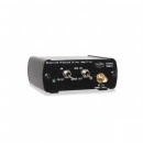
TBMDA1 Modulated Wideband Driver Amplifier
Tekbox Amplifiers
Product Description
The TBMDA1 modulated wideband driver amplifier is designed in order to create an inexpensive signal source for immunity testing of electronic building blocks and products. It is designed to be driven by the tracking generator output of spectrum analyzers. With its gain of 22 dB and 1dB compression point of +22dBm, it can boost the output power of a tracking generator up to 150mW. The TBMDA1 is ideal to drive Tekbox near field probes in order to find the sensitive spot of an electronic circuit or to create electric fields up to 50V/m when driving the Tekbox TEM Cell TBTC1, 25V/m when driving the TBTC2 or 18V/m when driving the TBTC3. Test signals for immunity testing can be CW, AM or PM. Consequently, the TBMDA1 provides built in modulation capability to generate 1kHz AM or PM signals. In PM mode, the TBMDA1 can also generate a 217Hz Signal with 12.5% duty cycle in order to simulate mobile phone TDMA noise.
FEATURES
CW amplifier (modulation off)
1 kHz, 80% AM modulation
1 kHz, 50% duty cycle pulse modulation
217 Hz, 12.5% duty cycle pulse modulation
SPECIFICATIONS
Input: 50 Ohm, SMA femaleOutput: 50 Ohm, SMA femaleNominal supply Voltage: 5V, typ. 235mA, Mini-USB-B connectorMaximum supply voltage: 5.5VMaximum input power: +9dBm1dB output compression point @ 40MHz: +21.5dBm1dB output compression point @ 2 GHz: +22.5dBm3rd order output intercept point @ 40 MHz: +39dBm3rd order output intercept point @ 2 GHz: +42dBmReverse isolation S12: -45dBNoise Figure: 3 … 4 dBInternal modulation frequency AM: 1 kHz ±10%
Documentation Download:
TBMDA1 manual
Application Note: Immunity testing example using Tekbox TEM Cells
Application note: How to correctly use spectrum analyzers for EMC pre-compliance tests
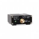
TBDA1 Wideband Driver Amplifiers
Tekbox Amplifiers
Product Description
TBDA1 wideband driver amplifiers are versatile building blocks that can easily be integrated into laboratory setups. With a frequency range of 40MHz to 3GHz and an output power of + 22 dBm at 1dB compression, they are ideal to boost the amplitude of low power RF sources or to drive power amplifier stages. The TBDA1 wideband amplifiers are available with 14dB or 28dB gain.
SPECIFICATIONS
TBDA1/14dB
Input: 50 Ohm, SMA femaleOutput: 50 Ohm, SMA femaleNominal supply Voltage: 5V, typ. 115mA, Mini-USB-B connectorMaximum supply voltage: 5.5VMaximum input power: +20dBm1dB output compression point @ 40MHz: +21.5dBm1dB output compression point @ 2 GHz: +22.5dBm3rd order output intercept point @ 40 MHz: +40dBm3rd order output intercept point @ 2 GHz: +43dBmReverse isolation S12: -20dBNoise Figure: 3 … 4 dB
Gain:
25 MHz
50 MHz
100 MHz
500 MHz
1 GHz
1.5 GHz
2 GHz
2.5 GHz
3 GHz
12 dB
13.8 dB
14.2 dB
14.2 dB
14.1 dB
14.2 dB
13.6 dB
13.8 dB
14 dB
TBDA1/28dB
Input: 50 Ohm, SMA femaleOutput: 50 Ohm, SMA femaleNominal supply Voltage: 5V, typ. 225mA, Mini-USB-B connectorMaximum supply voltage: 5.5VMaximum input power: +6 dBm1dB output compression point @ 40MHz: +21.5dBm1dB output compression point @ 2 GHz: +22.5dBm3rd order output intercept point @ 40 MHz: +39.8dBm3rd order output intercept point @ 2 GHz: +42.8dBmReverse isolation S12: < -40dBNoise Figure: 3.1 … 4.1 dB
Gain:
25 MHz
50 MHz
100 MHz
500 MHz
1 GHz
1.5 GHz
2 GHz
2.5 GHz
3 GHz
26 dB
28.4 dB
28.6 dB
28.6 dB
28.8 dB
28.3 dB
27.2dB
28.5 dB
28.9 dB
APPLICATION
general purpose gain block
RF driver amplifier
Documentation Downloads:
TBDA1 manual
Application note: How to correctly use spectrum analyzers for EMC pre-compliance tests
TBDA1_14 Gain File for EMCview
TBDA1_28 Gain File for EMCview
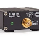
TBHDR1 High Dynamic Range Amplifier
Tekbox Amplifiers
Product Description
TBHDR1 High Dynamic Range Amplifier
The TBHDR1 is a high dynamic range amplifier with a frequency range from 30kHz to 1.5GHz. Its gain is characterized up to 6GHz.The TBHDR1 has a high IP3 and a low noise figure which makes it an ideal alternative pre-amplifier for spectrum analyzers and receivers in EMC test applications. Due to its low noise figure, high IP3 and gain down to the kHz range it also performs very well as amplifier for active loop antennas.
SPECIFICATIONS
Maximum supply voltage: 5.5VMaximum input power: +10 dBmInput, Output: 50 Ohm, SMA femaleNominal supply Voltage: 5V, typ. 100mA, Mini-USB-B connector1dB output compression point @ 100 MHz: +19.2 dBm typical1dB output compression point @ 500 MHz: +19 dBm typical1dB output compression point @ 1000 MHz: +18.3 dBm typical3rd order output intercept point @ 100 MHz: +38dBm3rd order output intercept point @ 500 MHz: +37dBm3rd order output intercept point @ 1000 MHz: +33dBmReverse isolation S12: -28dBInput matching: 30kHz-1.5GHz < – 16 dBOutput matching: 30kHz-1.5GHz < – 10 dBNoise Figure: 2.7 dB
Gain:
30 kHz
150 kHz
1 MHz
100 MHz
500 MHz
1 GHz
1.5 GHz
3 GHz
6 GHz
22.5 dB
23.6 dB
24.2 dB
24 dB
22.9 dB
21.1 dB
19.5 dB
14.1 dB
5.3 dB
APPLICATION
general purpose gain block
pre-amplifier in applications with low noise and high IP3 requirements
pre-amplifier for spectrum analyzers, especially in EMC pre-compliance test applications
Loop antenna amplifier
TBHDR1 manual
Application note: How to correctly use spectrum analyzers for EMC pre-compliance tests
TBHDR1 Gain File for EMCview
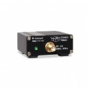
TBWA2/20dB, TBWA2/40dB
Tekbox Amplifiers
Product Description
Application:
EMC probe amplifier
General purpose wideband RF amplifier
TBWA2 wideband RF amplifiers are versatile building blocks that can easily be integrated into laboratory setups. With a bandwidth of 2MHz to 6GHz they are ideal to boost the signals picked up by our EMC near field probes. The TBWA2 wideband amplifiers are available with 20dB or 40dB gain.
TBHDR1
Application:
general purpose gain block
pre-amplifier in applications with low noise and high IP3 requirements
pre-amplifier for spectrum analyzers, especially in EMC pre-compliance test applications
Loop antenna amplifier
The TBHDR1 is a high dynamic range amplifier with a frequency range from 30kHz to 1.5GHz. Its gain is characterized up to 6GHz.The TBHDR1 has a high IP3 and a low noise figure which makes it an ideal alternative pre-amplifier for spectrum analyzers and receivers in EMC test applications. Due to its low noise figure, high IP3 and gain down to the kHz range it also performs very well as amplifier for active loop antennas.
TBDA1/14dB, TBDA1/28dB
Application:
RF driver amplifier
General purpose wideband RF amplifier
TBDA1 wideband driver amplifiers are versatile building blocks that can easily be integrated into laboratory setups. With a frequency range of 40MHz to 3GHz and an output power of + 22 dBm at 1dB compression, they are ideal to boost the amplitude of low power RF sources or to drive power amplifier stages. The TBDA1 wideband amplifiers are available with 14dB or 28dB gain.
TBMDA1
Application:
Pre-compliance RF immunity testing, driving Tekbox EMC probes or TEM cells
RF driver amplifier
General purpose wideband RF amplifier
The TBMDA1 modulated wideband driver amplifier is designed in order to create an inexpensive signal source for immunity testing of electronic building blocks and products. It is designed to be driven by the tracking generator output of spectrum analyzers. With its gain of 22 dB and 1dB compression point of +22dBm, it can boost the output power of a tracking generator up to 150mW. The TBMDA1 is ideal to drive Tekbox near field probes in order to find the sensitive spot of an electronic circuit or to create electric fields up to 50V/m when driving the Tekbox TEM Cell TBTC1, 25V/m when driving the TBTC2 or 18V/m when driving the TBTC3. Test signals for immunity testing can be CW, AM or PM. Consequently, the TBMDA1 provides built in modulation capability to generate 1kHz AM or PM signals. In PM mode, the TBMDA1 can also generate a 217Hz Signal with 12.5% duty cycle in order to simulate mobile phone TDMA noise.
TBMDA2
Application:
General-purpose gain block
Signal source for immunity testing, driving near field probes
Signal source for immunity testing, driving TEM Cells
The TBMDA2 modulated wideband driver amplifier is designed in order to create an inexpensive signal source for immunity testing of electronic building blocks and products. It is designed to be driven by the tracking generator output of spectrum analyzers. With its 1dB compression point of +27dBm, it can boost the output power of a tracking generator up to 500mW. The TBMDA2 is ideal to drive Tekbox near field probes in order to find the sensitive spot of an electronic circuit or to create electric fields up to 170V/m when driving the Tekbox TEM Cell TBTC0, 100V/m when driving the TBTC1, 50V/m when driving the TBTC2 or 30V/m when driving the TBTC3. Test signals for immunity testing can be CW, AM or PM. Consequently, the TBMDA2 provides built in modulation capability to generate 1 kHz AM or PM signals. In PM mode, the TBMDA2 can also generate a 217 Hz Signal with 12.5% duty cycle in order to simulate mobile phone TDMA noise.
TBMDA3
Application:
General-purpose power amplifier
Signal source for immunity testing, driving near field probes
Signal source for immunity testing, driving TEM Cells
The TBMDA3 modulated wideband power amplifier is designed in order to create an inexpensive signal source for immunity testing of electronic building blocks and products. It is designed to be driven by the tracking generator output of spectrum analyzers. With an input power range of -5dBm…0dBm, it can boost the output power of a tracking generator up to 5W. The TBMDA3 is ideal to drive Tekbox near field probes in order to find the sensitive spot of an electronic circuit or to create electric fields up to 550V/m when driving the Tekbox TEM Cell TBTC0, 300V/m when driving the TBTC1, 150V/m when driving the TBTC2 or 100V/m when driving the TBTC3. Test signals for immunity testing can be CW, AM or PM modulated. Consequently, the TBMDA3 provides built in modulation capability to generate 1 kHz AM or PM signals. In PM mode, the TBMDA3 can also generate a 217 Hz Signal with 12.5% duty cycle in order to simulate mobile phone TDMA noise.
Part Nr.
Frequency range [MHz]
Gain [dB] typ.
N.F. [dB] typ
Max. pwr. @ P1dB [dBm]
IP3 out
[dBm]
Max. input pwr. rating [dBm]
Supply voltage [V]
Supply current [mA]
Application
TBWA2/20dB
1.5 – 6000
20
4.5
20
35
10
5
110
EMC probe amplifier
TBWA2/40dB
2.5 – 6000
40
4.5
20
35
-10
5
210
EMC probe amplifier
TBHDR1
0.03 – 1500
24
2.7
19
38
10
5
100
Spectrum Analyser pre amplifier
TBDA1/14
20 – 3000
14
4
22
40
20
5
115
Wideband driver amplifier
TBDA1/28
20 – 3000
28
4
22
40
6
5
225
Wideband driver amplifier
TBMDA1
20 – 3000
20
4
22
40
9
5
235
RF immunity testing
TBMDA2
10 – 1500
40
4
27
40
-8
5
700
RF immunity testing
TBMDA3
10 – 1000
40
9
37
40
37
110-240
20 W
RF immunity testing
TBWA2 Wideband RF Amplifiers
Tekbox Amplifiers
Product Description
TBWA2 wideband RF amplifiers are versatile building blocks that can easily be integrated into laboratory setups. With a bandwidth of 2MHz to 6GHz, they are ideal to boost the signals picked up by our EMC near field probes. The TBWA2 wideband amplifiers are available with 20dB or 40dB gain.
SPECIFICATIONS
TBWA2/20dB
Input: 50 Ohm, SMAOutput: 50 Ohm, SMANominal supply Voltage: 4.5 – 5V, typ. 110mA, Mini-USB-B connectorMaximum supply voltage: 5.5VMaximum input power: +10dBm1dB output compression point @ 2GHz: +20dBm3rd order output intercept point @ 2GHz, Pin = 0dBm/tone, Δf = 10MHz: +35dBmReverse isolation S12, 0.1 …6GHz: 23dBNoise Figure @ 2GHz: 4.5 … 5 dB
Gain:
1 MHz
10 MHz
100 MHz
500 MHz
1 GHz
2 GHz
3 GHz
4.5 GHz
6 GHz
14.8 dB
20.2 dB
20.2 dB
20 dB
19.8 dB
19 dB
17.6 dB
17.4 dB
15.4 dB
TBWA2/40dB
Input: 50 Ohm, SMAOutput: 50 Ohm, SMANominal supply Voltage: 4.5 – 5V, typ. 210mA, Mini-USB-B connectorMaximum supply voltage: 5.5VMaximum input power: -10dBm1dB output compression point @ 2GHz: +20dBmReverse isolation S12, 0.1 …6GHz: 40dBNoise Figure @ 2GHz: 5 dB
Gain:
1 MHz
10 MHz
100 MHz
500 MHz
1 GHz
2 GHz
3 GHz
4.5 GHz
6 GHz
30 dB
40.2 dB
40.2 dB
40 dB
39.5 dB
37.6 dB
36.4 dB
34.6 dB
34.7 dB
APPLICATION
general purpose gain block
EMC probe amplifier
Tribrer | APM58 4in1 Li-lion Battery Optical Power Meter Visual Fault Locator Network Cable Test Optical Fiber Tester – 30KM
Power Meters and Light Sources
Product Description
Power detector type: ingaps
Power meter interface: 2.5mmgpi
Wave length range: 700-1700mm
Calibration wavelength: 850/1300/1310/1490/1550/1625nm
Measurement range: 50T-70-+10dbm
Accuracy: ia2db
Red light source interface: 2.5mm gpi
Output power of red light source: 1-30mw
Flashlight torch: yes
Network cable detection interface: rj45
Data interface: use
Battery built-in lithium battery(rechargeable)
Storage temperature: -20-60c<90%orh
Operating temperature: -10-50c<90%orh
Dimension: 59mmX98mmX27mm
Package includes:
1 X APM58 Optical Power Meter(5KM/15KM/30KM)
Please click here to download specifications:Click Here
Siglent SDS2204X HD 12-bit 200MHz Oscilloscope
Siglent Oscilloscopes
Product Description
The siglent SDS2204X HD is a 200MHz bandwidth high resolution digital storage oscilloscope that is based on 2 GSa/s sample rate and 12-bit Analog-Digital Convertor front ends w excellent noise floor performance.
The SDS2204X HD series employs Siglent’s SPO technology with a maximum waveform capture rate of up to 100,000 wfm/ s (normal mode, up to 500,000 wfm/s in Sequence mode), 256-level intensity grading display function plus a color temperature display mode. It also employs an innovative digital trigger system with high sensitivity and low jitter. The trigger system supports multiple powerful triggering modes including serial bus triggering. Tools such as History waveform recording, Search and Navigate functions, Mask Test, Bode Plot, Power Analysis and Histogram allow for extended waveform records to be captured, stored, and analyzed. An impressive array of measurement and math capabilities, options for a 25 MHz arbitrary waveform generator, as well as serial decoding are also features of the SDS2000X HD.
Excellent User Interface and User Experience
Bode Plot
The oscilloscope can control the built-in waveform generator or a stand-alone SIGLENT generator, to scan the amplitude and phase-frequency response of the DUT, and display the data as a Bode Plot. This makes it possible to replace expensive network analyzers in some applications
12-bit High Resolution
12-bit resolution shows you more details and less noise on the waveform.
Siglent SDS2204X HD Key Features
12-bit High Resolution.-12-bit Analog-Digital Convertors with sample rate up to 2 GSa/s.-Front ends with 70 μVrms noise floor @ 500 MHz bandwidth and 0.5% DC gain accuracy.
4 analog channels, up to 200 MHz bandwidth (upgradable to 500 MHz)]
SPO technology.-Waveform capture rate up to 100,000 wfm/s (normal mode), and 500,000 wfm/s (sequence mode).-Supports 256-level intensity grading and color temperature display modes.-Up to 200 Mpts/ch record length.-Digital trigger system.
Intelligent trigger: Edge, Slope, Pulse, Window, Runt, Interval, Dropout, Pattern, Qualified, Nth edge, Setup/hold, Delay and Video (HDTV supported). Zone Trigger simplifies advanced triggering.
Serial bus triggering and decoder, supports protocols I2C, SPI, UART, CAN, LIN, CAN FD, FlexRay, I2S, MIL-STD-1553B, SENT and Manchester
Segmented acquisition (Sequence) mode, dividing the maximum record length into multiple segments (up to 80,000), according to trigger conditions set by the user, with a very small dead time between segments to capture the qualifying event.
History waveform record (History) function, the maximum recorded waveform length is 80,000 frames.
Automatic measurements on 50+ parameters, supports statistics with histogram, track, trend, Gating measurement, and measurements on Math, History and Ref.
2 Math traces (2 Mpts FFT, addition, subtraction, multiplication, division, integration, differential, square root, etc.), supports formula editor.
Abundant data analysis functions such as Search, Navigate, Digital Voltmeter, Counter, Waveform Histogram, Bode plot and Power Analysis.
High Speed hardware-based Average, ERES; High Speed hardware-based Mask Test function, with Mask Editor tool for creating user-defined masks.
16 digital channels (optional).
Built-in 25 MHz waveform generator.
Large 10.1” TFT-LCD display with 1024 * 600 resolution; Capacitive touch screen supports multi-touch gestures.
Interfaces include: USB Hosts, USB Device (USBTMC), LAN (VXI-11/Telnet/Socket), Pass/Fail, Trigger Out.
Built-in web server supports remote control over the LAN port using a web browser. Supports SCPI remote control commands. Supports external mouse and keyboard
Model
SDS2204X HD
Bandwidth
200 MHz (Upgradable to 500 MHz max.)
Sampling Rate (Max.)
2 GSa/s (interleaving mode), 1 GSa/s (non-interleaving mode)
Channels
4+ EXT
Memory Depth (Max.)
200 Mpts/ch (interleaving mode),100 Mpts/ch (non-interleaving mode)
Waveform Capture Rate (Max.)
Normal mode:100,000 wfm/s; Sequence mode:500,000 wfm/s
Trigger Types
Edge, Slope, Pulse width, Window, Runt, Interval, Dropout, Pattern, Video, Qualified, Nth edge, Setup/hold, Delay, Serial
Serial Trigger & Decoding
Standard: I2C, SPI, UART, CAN, LIN Optional: CAN FD, FlexRay, I2S, MIL-STD-1553B, SENT, Manchester (decode only)
Measurement
50+ parameters, statistics, histogram, trend, and track supported
Math
2 traces 2 Mpts FFT, +, -, x, ÷, ∫dt, d/dt, √, Identity, Negation, Absolute, Sign, ex, 10x, ln, lg, Interpolation, MaxHold, MinHold, ERES, Average. Supports formula editor
Data analysis
Search, Navigate, History, Mask Test, Digital Voltmeter, Counter, Waveform Histogram, Bode plot, and Power Analysis
Digital channel (optional)
16-channel; maximum sample rate up to 500 MSa/s; record length up to 50 Mpts
Waveform generator (optional)
Single-channel built-in waveform generator, frequency up to 25 MHz, 125 MSa/s sample rate, 16 kpts waveform memory
I/O
USB 2.0 Host x3, USB 2.0 Device, 10 M / 100 M LAN, External trigger, Auxiliary output (TRIG OUT, PASS/FAIL)
Probe (Standard)
One 500 MHz passive probe supplied for each channel
Display
10.1 TFT-LCD with capacitive touch screen (1024*600)
Standard Accessories
1 x USB cable1 x Quick start4 x Passive probe ( 500 MHz)1 x Certificate of calibration1 x Wireless mouse1 x Power cord
Siglent SDS2104X HD 12-bit 100MHz Oscilloscope
Siglent Oscilloscopes
Product Description
The siglent SDS2104X HD is a 100MHz bandwidth high resolution digital storage oscilloscope that is based on 2 GSa/s sample rate and 12-bit Analog-Digital Convertor front ends w excellent noise floor performance.
The SDS2104X HD series employs Siglent’s SPO technology with a maximum waveform capture rate of up to 100,000 wfm/ s (normal mode, up to 500,000 wfm/s in Sequence mode), 256-level intensity grading display function plus a color temperature display mode. It also employs an innovative digital trigger system with high sensitivity and low jitter. The trigger system supports multiple powerful triggering modes including serial bus triggering. Tools such as History waveform recording, Search and Navigate functions, Mask Test, Bode Plot, Power Analysis and Histogram allow for extended waveform records to be captured, stored, and analyzed. An impressive array of measurement and math capabilities, options for a 25 MHz arbitrary waveform generator, as well as serial decoding are also features of the SDS2000X HD.
Excellent User Interface and User Experience
Bode Plot
The oscilloscope can control the built-in waveform generator or a stand-alone SIGLENT generator, to scan the amplitude and phase-frequency response of the DUT, and display the data as a Bode Plot. This makes it possible to replace expensive network analyzers in some applications
12-bit High Resolution
12-bit resolution shows you more details and less noise on the waveform.
Siglent SDS2104X HD Key Features
12-bit High Resolution.-12-bit Analog-Digital Convertors with sample rate up to 2 GSa/s.-Front ends with 70 μVrms noise floor @ 500 MHz bandwidth and 0.5% DC gain accuracy.
4 analog channels, up to 200 MHz bandwidth (upgradable to 500 MHz)]
SPO technology.-Waveform capture rate up to 100,000 wfm/s (normal mode), and 500,000 wfm/s (sequence mode).-Supports 256-level intensity grading and color temperature display modes.-Up to 200 Mpts/ch record length.-Digital trigger system.
Intelligent trigger: Edge, Slope, Pulse, Window, Runt, Interval, Dropout, Pattern, Qualified, Nth edge, Setup/hold, Delay and Video (HDTV supported). Zone Trigger simplifies advanced triggering.
Serial bus triggering and decoder, supports protocols I2C, SPI, UART, CAN, LIN, CAN FD, FlexRay, I2S, MIL-STD-1553B, SENT and Manchester
Segmented acquisition (Sequence) mode, dividing the maximum record length into multiple segments (up to 80,000), according to trigger conditions set by the user, with a very small dead time between segments to capture the qualifying event.
History waveform record (History) function, the maximum recorded waveform length is 80,000 frames.
Automatic measurements on 50+ parameters, supports statistics with histogram, track, trend, Gating measurement, and measurements on Math, History and Ref.
2 Math traces (2 Mpts FFT, addition, subtraction, multiplication, division, integration, differential, square root, etc.), supports formula editor.
Abundant data analysis functions such as Search, Navigate, Digital Voltmeter, Counter, Waveform Histogram, Bode plot and Power Analysis.
High Speed hardware-based Average, ERES; High Speed hardware-based Mask Test function, with Mask Editor tool for creating user-defined masks.
16 digital channels (optional).
Built-in 25 MHz waveform generator.
Large 10.1” TFT-LCD display with 1024 * 600 resolution; Capacitive touch screen supports multi-touch gestures.
Interfaces include: USB Hosts, USB Device (USBTMC), LAN (VXI-11/Telnet/Socket), Pass/Fail, Trigger Out.
Built-in web server supports remote control over the LAN port using a web browser. Supports SCPI remote control commands. Supports external mouse and keyboard
Model
SDS2104X HD
Bandwidth
100 MHz (Upgradable to 500 MHz max.)
Sampling Rate (Max.)
2 GSa/s (interleaving mode), 1 GSa/s (non-interleaving mode)
Channels
4+ EXT
Memory Depth (Max.)
200 Mpts/ch (interleaving mode),100 Mpts/ch (non-interleaving mode)
Waveform Capture Rate (Max.)
Normal mode:100,000 wfm/s; Sequence mode:500,000 wfm/s
Trigger Types
Edge, Slope, Pulse width, Window, Runt, Interval, Dropout, Pattern, Video, Qualified, Nth edge, Setup/hold, Delay, Serial
Serial Trigger & Decoding
Standard: I2C, SPI, UART, CAN, LIN Optional: CAN FD, FlexRay, I2S, MIL-STD-1553B, SENT, Manchester (decode only)
Measurement
50+ parameters, statistics, histogram, trend, and track supported
Math
2 traces 2 Mpts FFT, +, -, x, ÷, ∫dt, d/dt, √, Identity, Negation, Absolute, Sign, ex, 10x, ln, lg, Interpolation, MaxHold, MinHold, ERES, Average. Supports formula editor
Data analysis
Search, Navigate, History, Mask Test, Digital Voltmeter, Counter, Waveform Histogram, Bode plot, and Power Analysis
Digital channel (optional)
16-channel; maximum sample rate up to 500 MSa/s; record length up to 50 Mpts
Waveform generator (optional)
Single-channel built-in waveform generator, frequency up to 25 MHz, 125 MSa/s sample rate, 16 kpts waveform memory
I/O
USB 2.0 Host x3, USB 2.0 Device, 10 M / 100 M LAN, External trigger, Auxiliary output (TRIG OUT, PASS/FAIL)
Probe (Standard)
One 500 MHz passive probe supplied for each channel
Display
10.1 TFT-LCD with capacitive touch screen (1024*600)
Standard Accessories
1 x USB cable1 x Quick start4 x Passive probe ( 500 MHz)1 x Certificate of calibration1 x Wireless mouse1 x Power cord
Siglent SDS6204A 4CH 2GHz 5 GSa/s Oscilloscope
Siglent Oscilloscopes
Product Description
SIGLENT’s NEW SDS6204A 4 Channel Digital Storage Oscilloscope with 2 GHz bandwidth, has a sample rate of 5 GSa/s (10 GSa/s ESR) at each channel, maximum record length of 500 Mpts/ch (single-channel), and display up to 4 analog channels + 16 digital channels mixed signal analysis ability. With Eye diagram, jitter analysis options.
The SDS6204A Oscilloscope employs Siglent’s SPO technology with a maximum waveform capture rate of up to 170,000 wfm/ s (normal mode, up to 750,000 wfm/s in Sequence mode), 256- level intensity grading display function plus a color temperature display mode. It also employs an innovative digital trigger system with high sensitivity and low jitter. The trigger system supports multiple powerful triggering modes including serial bus triggering.
Tools such as History waveform recording, Search and Navigate functions, Mask Test, Bode Plot, Power Analysis and Eye/Jitter Analysis allow for extended waveform records to be captured, stored, and analyzed. An impressive array of measurement and math capabilities, options for a 25 MHz arbitrary waveform generator, as well as serial decoding are also features of the SDS6204A.
The large 12.1’’ display capacitive touch screen supports multi-touch gestures, with the addition of user-friendly UI design, can greatly improve the operation efficiency. It also supports mouse control, and remote web control over LAN
Excellent User Interface and User Experience
Bode Plot
The oscilloscope can control the isolated USB AWG module or a stand-alone SIGLENT SDG generator, to scan the amplitude and phase-frequency response of the DUT, and display the data as a Bode Plot. This makes it possible to replace expensive network analyzers in some applications
Power Analysis (Optional)
The Power Analysis option provides a full suite of power measurements and analysis, which greatly improve the measurement efficiency in switching power supplies and power devices design
Key Features SDS6000A Series
4 analog channels, up to 2 GHz bandwidth with 5 GSa/s (10 GSa/s ESR) sample rate at each channel.Low background noise, supports 0.5 mV/div to 10 V/div vertical scales.SPO technology
Waveform capture rates up to 170,000 wfm/s (normal mode), and 750,000 wfm/s (sequence mode)
Supports 256-level intensity grading and color temperature display modes
500 Mpts Record length in total for all 4 channels
Digital trigger system
Intelligent trigger: Edge, Slope, Pulse, Window, Runt, Interval, Dropout, Pattern, Qualified, Nth edge, Setup/hold, Delay and Video (HDTV supported). Zone Trigger simplifies advanced triggering Serial bus triggering and decoder, supports protocols I 2 C, SPI, UART, CAN, LIN, CAN FD, FlexRay, I 2 S, MIL- STD-1553B, SENT and Manchester.Segmented acquisition (Sequence) mode, dividing the maximum record length into multiple segments (up to 80,000), according to trigger conditions set by the user, with a very small dead time between segments to capture the qualifying event. History waveform record (History) function, the maximum recorded waveform length is 80,000 frames.Automatic measurements on 50+ parameters, supports statistics with histogram, track, trend, Gating measurement, and measurements on Math, History and Ref4 Math traces (8 Mpts FFT, addition, subtraction, multiplication, division, integration, differential, square root, etc.), supports formula editor.Abundant data analysis functions such as Search, Navigate, Digital Voltmeter, Counter, Waveform Histogram, Bode plot, Power Analysis and Eye/Jitter Analysis. High Speed hardware-based Average, Hi-Res; High Speed hardware-based Mask Test function, with Mask Editor tool for creating user-defined masks.16 digital channels (optional)25 MHz function / arbitrary waveform generator, built-in multiple predefined waveformsLarge 12.1” TFT-LCD display with 1280 * 800 resolution; Capacitive touch screen supports multi-touch gestures.Interfaces include: USB Hosts, USB Device (USBTMC), LAN(VXI-11/ Telnet/ Socket), micro SD card, Pass/Fail, Trigger Out, HDMI.Built-in web server supports remote control over the LAN port using a web browser. Supports SCPI remote control commands. Supports external mouse and keyboard
Complete Connectivity
Model
SDS6204A
Analog channels
4 + EXT
Bandwidth
2 GHz
Sample rate (Max.)
5 GSa/s (10 GSa/s ESR) @ each channel
Waveform capturerate (Max.)
500 Mpts/ch(single-channel), 250 Mpts/ch (dual-channel), 125 Mpts/ch (3 or 4 channels)
Vertical resolution
8-bit, up to 16-bit in Hi-Res mode
Trigger type
Edge, Slope, Pulse width, Window, Runt, Interval, Dropout, Pattern, Video, Qualified, Nth edge, Setup/hold, Delay, Serial
Serial trigger and decode
Standard: I 2 C, SPI, UART, CAN, LIN, Optional: CAN FD, FlexRay, I 2 S, MIL-STD-1553B, SENT, Manchester (decode only)
Measurement
50+ parameters,statistics, histogram, trend, and track supported
Math
4 traces 8 Mpts FFT, +, -, x, ÷, ∫dt, d/dt, √, Identity, Negation, Absolute, Sign, e x , 10 x , ln, lg, Interpolation, MaxHold, MinHold. Supports formula editor
Data analysis
Search, Navigate, History, Mask Test, Digital Voltmeter, Counter, Waveform Histogram, Bode plot and Power Analysis, Eye/Jitter Analysis
Digital channel (optional)
16-channel; maximum sample rate up to 1 GSa/s; record length up to 50 Mpts
Waveform generator (optional)
Single-channel external USB isolated waveform generator, frequency up to 25 MHz, 125 MSa/s sample rate, 16 kpts waveform memory
I/O
USB 3.0 Host x2,USB 2.0 Host x2,USB 2.0 Device,LAN,micro SD card, HDMI, External trigger, Auxiliary output(TRIG OUT,PASS/FAIL)
Probe (Standard)
SP3050A, 500 MHz, 1 probe supplied for each channel
Display
12.1 TFT-LCD with capacitive touch screen (1280*800)
Download Specifications Here:Click Here
Accessoires Included:
1 x USB cable1 x Quick start4 x Passive probe (SP3050A)1 x Certificate of calibration1 x Wireless mouse1 x Power cord
Siglent SDS6104A 4CH 1GHz 5 GSa/s Oscilloscope
Siglent Oscilloscopes
Product Description
SIGLENT’s NEW SDS6104A 4 Channel Digital Storage Oscilloscope with 1 GHz bandwidth, has a sample rate of 5 GSa/s (10 GSa/s ESR) at each channel, maximum record length of 500 Mpts/ch (single-channel), and display up to 4 analog channels + 16 digital channels mixed signal analysis ability.
The SDS6204A Oscilloscope employs Siglent’s SPO technology with a maximum waveform capture rate of up to 170,000 wfm/ s (normal mode, up to 750,000 wfm/s in Sequence mode), 256- level intensity grading display function plus a color temperature display mode. It also employs an innovative digital trigger system with high sensitivity and low jitter. The trigger system supports multiple powerful triggering modes including serial bus triggering.
Tools such as History waveform recording, Search and Navigate functions, Mask Test, Bode Plot, Power Analysis and Eye/Jitter Analysis allow for extended waveform records to be captured, stored, and analyzed. An impressive array of measurement and math capabilities, options for a 25 MHz arbitrary waveform generator, as well as serial decoding are also features of the SDS6204A.
The large 12.1’’ display capacitive touch screen supports multi-touch gestures, with the addition of user-friendly UI design, can greatly improve the operation efficiency. It also supports mouse control, and remote web control over LAN
Excellent User Interface and User Experience
Bode Plot
The oscilloscope can control the isolated USB AWG module or a stand-alone SIGLENT SDG generator, to scan the amplitude and phase-frequency response of the DUT, and display the data as a Bode Plot. This makes it possible to replace expensive network analyzers in some applications
Power Analysis (Optional)
The Power Analysis option provides a full suite of power measurements and analysis, which greatly improve the measurement efficiency in switching power supplies and power devices design
Key Features SDS6000A Series
4 analog channels, up to 2 GHz bandwidth with 5 GSa/s (10 GSa/s ESR) sample rate at each channel.Low background noise, supports 0.5 mV/div to 10 V/div vertical scales.SPO technology
Waveform capture rates up to 170,000 wfm/s (normal mode), and 750,000 wfm/s (sequence mode)
Supports 256-level intensity grading and color temperature display modes
500 Mpts Record length in total for all 4 channels
Digital trigger system
Intelligent trigger: Edge, Slope, Pulse, Window, Runt, Interval, Dropout, Pattern, Qualified, Nth edge, Setup/hold, Delay and Video (HDTV supported). Zone Trigger simplifies advanced triggeringSerial bus triggering and decoder, supports protocols I 2 C, SPI, UART, CAN, LIN, CAN FD, FlexRay, I 2 S, MIL- STD-1553B, SENT and Manchester.Segmented acquisition (Sequence) mode, dividing the maximum record length into multiple segments (up to 80,000), according to trigger conditions set by the user, with a very small dead time between segments to capture the qualifying event. History waveform record (History) function, the maximum recorded waveform length is 80,000 frames.Automatic measurements on 50+ parameters, supports statistics with histogram, track, trend, Gating measurement, and measurements on Math, History and Ref4 Math traces (8 Mpts FFT, addition, subtraction, multiplication, division, integration, differential, square root, etc.), supports formula editor.Abundant data analysis functions such as Search, Navigate, Digital Voltmeter, Counter, Waveform Histogram, Bode plot, Power Analysis and Eye/Jitter Analysis. High Speed hardware-based Average, Hi-Res; High Speed hardware-based Mask Test function, with Mask Editor tool for creating user-defined masks.16 digital channels (optional)25 MHz function / arbitrary waveform generator, built-in multiple predefined waveformsLarge 12.1” TFT-LCD display with 1280 * 800 resolution; Capacitive touch screen supports multi-touch gestures.Interfaces include: USB Hosts, USB Device (USBTMC), LAN(VXI-11/ Telnet/ Socket), micro SD card, Pass/Fail, Trigger Out, HDMI.Built-in web server supports remote control over the LAN port using a web browser. Supports SCPI remote control commands. Supports external mouse and keyboard
Complete Connectivity
Model
SDS6204A
Analog channels
4 + EXT
Bandwidth
2 GHz
Sample rate (Max.)
5 GSa/s (10 GSa/s ESR) @ each channel
Waveform capturerate (Max.)
500 Mpts/ch(single-channel), 250 Mpts/ch (dual-channel), 125 Mpts/ch (3 or 4 channels)
Vertical resolution
8-bit, up to 16-bit in Hi-Res mode
Trigger type
Edge, Slope, Pulse width, Window, Runt, Interval, Dropout, Pattern, Video, Qualified, Nth edge, Setup/hold, Delay, Serial
Serial trigger and decode
Standard: I 2 C, SPI, UART, CAN, LIN, Optional: CAN FD, FlexRay, I 2 S, MIL-STD-1553B, SENT, Manchester (decode only)
Measurement
50+ parameters,statistics, histogram, trend, and track supported
Math
4 traces 8 Mpts FFT, +, -, x, ÷, ∫dt, d/dt, √, Identity, Negation, Absolute, Sign, e x , 10 x , ln, lg, Interpolation, MaxHold, MinHold. Supports formula editor
Data analysis
Search, Navigate, History, Mask Test, Digital Voltmeter, Counter, Waveform Histogram, Bode plot and Power Analysis, Eye/Jitter Analysis
Digital channel (optional)
16-channel; maximum sample rate up to 1 GSa/s; record length up to 50 Mpts
Waveform generator (optional)
Single-channel external USB isolated waveform generator, frequency up to 25 MHz, 125 MSa/s sample rate, 16 kpts waveform memory
I/O
USB 3.0 Host x2,USB 2.0 Host x2,USB 2.0 Device,LAN,micro SD card, HDMI, External trigger, Auxiliary output(TRIG OUT,PASS/FAIL)
Probe (Standard)
SP3050A, 500 MHz, 1 probe supplied for each channel
Display
12.1 TFT-LCD with capacitive touch screen (1280*800)
Download Specifications Here:Click Here
Accessoires Included:
1 x USB cable1 x Quick start4 x Passive probe (SP3050A)1 x Certificate of calibration1 x Wireless mouse1 x Power cord
Siglent SDS6054A 4CH 500MHz 5 GSa/s Oscilloscope
Siglent Oscilloscopes
Product Description
SIGLENT’s NEW SDS6054A 4 Channel Digital Storage Oscilloscope with 500 MHz bandwidth, has a sample rate of 5 GSa/s (10 GSa/s ESR) at each channel, maximum record length of 500 Mpts/ch (single-channel), and display up to 4 analog channels + 16 digital channels mixed signal analysis ability.
The SDS6204A Oscilloscope employs Siglent’s SPO technology with a maximum waveform capture rate of up to 170,000 wfm/ s (normal mode, up to 750,000 wfm/s in Sequence mode), 256- level intensity grading display function plus a color temperature display mode. It also employs an innovative digital trigger system with high sensitivity and low jitter. The trigger system supports multiple powerful triggering modes including serial bus triggering.
Tools such as History waveform recording, Search and Navigate functions, Mask Test, Bode Plot, Power Analysis and Eye/Jitter Analysis allow for extended waveform records to be captured, stored, and analyzed. An impressive array of measurement and math capabilities, options for a 25 MHz arbitrary waveform generator, as well as serial decoding are also features of the SDS6204A.
The large 12.1’’ display capacitive touch screen supports multi-touch gestures, with the addition of user-friendly UI design, can greatly improve the operation efficiency. It also supports mouse control, and remote web control over LAN
Excellent User Interface and User Experience
Bode Plot
The oscilloscope can control the isolated USB AWG module or a stand-alone SIGLENT SDG generator, to scan the amplitude and phase-frequency response of the DUT, and display the data as a Bode Plot. This makes it possible to replace expensive network analyzers in some applications
Power Analysis (Optional)
The Power Analysis option provides a full suite of power measurements and analysis, which greatly improve the measurement efficiency in switching power supplies and power devices design
Key Features SDS6000A Series
4 analog channels, up to 2 GHz bandwidth with 5 GSa/s (10 GSa/s ESR) sample rate at each channel.Low background noise, supports 0.5 mV/div to 10 V/div vertical scales.SPO technology
Waveform capture rates up to 170,000 wfm/s (normal mode), and 750,000 wfm/s (sequence mode)
Supports 256-level intensity grading and color temperature display modes
500 Mpts Record length in total for all 4 channels
Digital trigger system
Intelligent trigger: Edge, Slope, Pulse, Window, Runt, Interval, Dropout, Pattern, Qualified, Nth edge, Setup/hold, Delay and Video (HDTV supported). Zone Trigger simplifies advanced triggeringSerial bus triggering and decoder, supports protocols I 2 C, SPI, UART, CAN, LIN, CAN FD, FlexRay, I 2 S, MIL- STD-1553B, SENT and Manchester.Segmented acquisition (Sequence) mode, dividing the maximum record length into multiple segments (up to 80,000), according to trigger conditions set by the user, with a very small dead time between segments to capture the qualifying event. History waveform record (History) function, the maximum recorded waveform length is 80,000 frames.Automatic measurements on 50+ parameters, supports statistics with histogram, track, trend, Gating measurement, and measurements on Math, History and Ref4 Math traces (8 Mpts FFT, addition, subtraction, multiplication, division, integration, differential, square root, etc.), supports formula editor.Abundant data analysis functions such as Search, Navigate, Digital Voltmeter, Counter, Waveform Histogram, Bode plot, Power Analysis and Eye/Jitter Analysis. High Speed hardware-based Average, Hi-Res; High Speed hardware-based Mask Test function, with Mask Editor tool for creating user-defined masks.16 digital channels (optional)25 MHz function / arbitrary waveform generator, built-in multiple predefined waveformsLarge 12.1” TFT-LCD display with 1280 * 800 resolution; Capacitive touch screen supports multi-touch gestures.Interfaces include: USB Hosts, USB Device (USBTMC), LAN(VXI-11/ Telnet/ Socket), micro SD card, Pass/Fail, Trigger Out, HDMI.Built-in web server supports remote control over the LAN port using a web browser. Supports SCPI remote control commands. Supports external mouse and keyboard
Complete Connectivity
Model
SDS6204A
Analog channels
4 + EXT
Bandwidth
2 GHz
Sample rate (Max.)
5 GSa/s (10 GSa/s ESR) @ each channel
Waveform capturerate (Max.)
500 Mpts/ch(single-channel), 250 Mpts/ch (dual-channel), 125 Mpts/ch (3 or 4 channels)
Vertical resolution
8-bit, up to 16-bit in Hi-Res mode
Trigger type
Edge, Slope, Pulse width, Window, Runt, Interval, Dropout, Pattern, Video, Qualified, Nth edge, Setup/hold, Delay, Serial
Serial trigger and decode
Standard: I 2 C, SPI, UART, CAN, LIN, Optional: CAN FD, FlexRay, I 2 S, MIL-STD-1553B, SENT, Manchester (decode only)
Measurement
50+ parameters,statistics, histogram, trend, and track supported
Math
4 traces 8 Mpts FFT, +, -, x, ÷, ∫dt, d/dt, √, Identity, Negation, Absolute, Sign, e x , 10 x , ln, lg, Interpolation, MaxHold, MinHold. Supports formula editor
Data analysis
Search, Navigate, History, Mask Test, Digital Voltmeter, Counter, Waveform Histogram, Bode plot and Power Analysis, Eye/Jitter Analysis
Digital channel (optional)
16-channel; maximum sample rate up to 1 GSa/s; record length up to 50 Mpts
Waveform generator (optional)
Single-channel external USB isolated waveform generator, frequency up to 25 MHz, 125 MSa/s sample rate, 16 kpts waveform memory
I/O
USB 3.0 Host x2,USB 2.0 Host x2,USB 2.0 Device,LAN,micro SD card, HDMI, External trigger, Auxiliary output(TRIG OUT,PASS/FAIL)
Probe (Standard)
SP3050A, 500 MHz, 1 probe supplied for each channel
Display
12.1 TFT-LCD with capacitive touch screen (1280*800)
Accessoires Included:
1 x USB cable1 x Quick start4 x Passive probe (SP3050A)1 x Certificate of calibration1 x Wireless mouse1 x Power cord
Siglent SHS1202X 200MHz isolated 2CH Handheld Digital Oscilloscope
Siglent Oscilloscopes
Product Description
Siglent's new SHS1000X series is the great new tool for working on service and support cases in the field, outside the lab environment, the SHS1000X series delivers the right performance, flexibility and robustness. The handheld multimeter, handheld oscilloscope are standard tools when it comes to signal analysis. Siglent's new SHS1000X series of handheld oscilloscopes which delivers benchtop oscilloscope performance in handheld format and also supply a multimeter in the same chassis. They also offer many powerful features and long battery life in a portable, IP51 package.
Siglent SHS1202X Key Features:
200 MHz bandwidth models Sample rate of 1 GSa/s (single-channel), Sample rate of 500 MSa/s (two-channels). The Siglent
SPO technology:-Waveform capture rates up to 100,000 wfm/s (normal mode) and 400,000 wfm/s (sequence mode).-Supports 256-level intensity grading and color temperature.-Record length up to 12 Mpts.-Digital trigger system
Intelligent trigger: Edge, Slope, Pulse Width, Window, Runt, Interval, Time out (Dropout), Pattern
Serial bus triggering and decoding (Standard) for IIC, SPI, UART, CAN, and LIN protocols
Video trigger/HDTV
Low background noise with voltage scales from 2 mV/div to 100 V/div
3 one-button shortcuts for Oscilloscope, Multimeter and Recorder functions
8 one-button shortcuts for: Run/Stop, Auto Setup, Default, Measure, Cursors, Display/Persist, Clear Sweep and Print. More function shortcuts available when combined with the shift button.
Segmented acquisition (Sequence) mode, divides the maximum record length into multiple segments (up to 80,000), according to trigger conditions set by the user, with a very small dead time segment to capture the qualifying event.
History waveform record (History) function (maximum recorded waveform length is 80,000 frames).
Automatic measurement function for 38 parameters as well as Measurement Statistics, Zoom, Gating, Math, History and Reference functions.
1 Mpts FFT. Support Peaks and Markers.
Math and measurement functions use all sampled data points (up to 12 Mpts).
Math functions (FFT, addition, subtraction, multiplication, division, integration, differential, square root).
Default key can be customized for user settings or factory “defaults”
Supports Multi-language display and embedded online help.
Security Erase mode.
Search and navigate function.
Includes Recorder mode, including Sample and Measurement Loggers
6000 counts Digital Multimeter, Support DCV, ACV, DCI, ACI, Resistance, Diode, Capacitance, Continuity test.
True RMS AC Voltage/Current measurement multimeter.
5.6-inch TFT-LCD display with 640 * 480 resolution.
Interface types: Isolated USB Host, USB Device (MicroUSB -TMC)
Supports SCPI remote control commands.
UL2054 certified lithium battery pack, 6900 mAh capacity, external charger.
IP Rating: IP51.
Compliance with UL61010-1, UL61010-2-030, UL61010-2-033
Standard Serial trigger and decode
Standard Serial trigger and decoding: IIC, SPI, UART, CAN, LIN, widely used in automotive and embedded industries. Because of its unique portable design and battery power supply, it can better meet the testing needs of the automotive and embedded industries that require on-site decoding.
Full Isolation CATIII 600 Vrms, CATII 1000 Vrms
SHS1000X series features full isolation between the two oscilloscope channels, one multimeter channel, power adapter and the USB host/device port. The full isolation makes it ideal for both laboratory and floating signal measurement because it reduces the risk of accidental short circuits.
6000 Counts Digital Multimeter
Model
SHS810X
SHS820X
SHS1102X
SHS1202X
Bandwidth
100 MHz
200 MHz
100 MHz
200 MHz
Sample rate (Max.)
Two-channel share a single 1 GSa/s ADC. When two channels are enabled, each channel has a maximum sample rate of 500 MSa/s.When a single channel is active, that channel has a sample rate of 1 GSa/s
Channels
2 analog oscilloscope channels, 1 multimeter channel
Memory depth (Max.)
6 Mpts/CH (dual-channel mode) 12 Mpts/CH (single channel mode)
Waveform capture rate (Max.)
100,000 wfm/s (normal mode), 400,000 wfm/s (sequence mode)
Trigger type
Edge, Slope, Pulse Width, Window, Runt, Interval, Dropout, Pattern, Video
Serial Trigger and decoder
IIC, SPI, UART, CAN, LIN
Data Logger(Recorder)
Sample Logger. The Max sample rate is 25 kSa/s, the Min sample rate is 1 Sa/sMeasurement Logger. The Max interval is 10 minutes, the Min interval is 0.1second. The Max items of logging is 4
I/O
USB Host, USB Device
Max input Voltage (Scope)
CAT II 300 Vrms Between BNC Signal and Protecting EarthCAT II 30 Vrms Between BNC GND and Protecting EarthCAT II 300 Vrms Between BNC Signal and BNC GND
CAT III 600 Vrms, CAT II 1000 Vrms Between BNC Signal and Protecting EarthCAT III 600 Vrms, CAT II 1000 Vrms Between BNC GND and Protecting EarthCAT III 300 Vrms Between BNC Signal and BNC GND
Max input Voltage (Meter)
CAT III 300 Vrms Between BNC Signal and BNC GND
CAT III 600 Vrms, CAT II 1000 Vrms
Probe
PP510
PP215
PB925
Display
5.6-inch TFT-LCD (640x480)
Weight
Without package 1.75 kg. With package 3.5 kg
Download Specifications Here:Click Here
Accessoires Included:
1 x Siglent SHS1202X Handheld Oscilloscope1 x 6900 mAh battery2 x PB925 250 MHz Oscilloscope Probe2 x Current Adapter ( 1 x SCD600MA / 1 x SCD10A )1 x Multimeter probes set1 x Power adapter / charger1 x USB Cable1 x Quick Start Guide
Siglent SHS1102X 100MHz isolated 2CH Handheld Digital Oscilloscope
Siglent Oscilloscopes
Product Description
Siglent's new SHS1000X series is the great new tool for working on service and support cases in the field, outside the lab environment, the SHS1000X series delivers the right performance, flexibility and robustness. The handheld multimeter, handheld oscilloscope are standard tools when it comes to signal analysis. Siglent's new SHS1000X series of handheld oscilloscopes which delivers benchtop oscilloscope performance in handheld format and also supply a multimeter in the same chassis. They also offer many powerful features and long battery life in a portable, IP51 package.
Siglent SHS1102X Key Features:
100 MHz bandwidth models Sample rate of 1 GSa/s (single-channel), Sample rate of 500 MSa/s (two-channels). The Siglent
SPO technology:-Waveform capture rates up to 100,000 wfm/s (normal mode) and 400,000 wfm/s (sequence mode).-Supports 256-level intensity grading and color temperature.-Record length up to 12 Mpts.-Digital trigger system
Intelligent trigger: Edge, Slope, Pulse Width, Window, Runt, Interval, Time out (Dropout), Pattern
Serial bus triggering and decoding (Standard) for IIC, SPI, UART, CAN, and LIN protocols
Video trigger/HDTV
Low background noise with voltage scales from 2 mV/div to 100 V/div
3 one-button shortcuts for Oscilloscope, Multimeter and Recorder functions
8 one-button shortcuts for: Run/Stop, Auto Setup, Default, Measure, Cursors, Display/Persist, Clear Sweep and Print. More function shortcuts available when combined with the shift button.
Segmented acquisition (Sequence) mode, divides the maximum record length into multiple segments (up to 80,000), according to trigger conditions set by the user, with a very small dead time segment to capture the qualifying event.
History waveform record (History) function (maximum recorded waveform length is 80,000 frames).
Automatic measurement function for 38 parameters as well as Measurement Statistics, Zoom, Gating, Math, History and Reference functions.
1 Mpts FFT. Support Peaks and Markers.
Math and measurement functions use all sampled data points (up to 12 Mpts).
Math functions (FFT, addition, subtraction, multiplication, division, integration, differential, square root).
Default key can be customized for user settings or factory “defaults”
Supports Multi-language display and embedded online help.
Security Erase mode.
Search and navigate function.
Includes Recorder mode, including Sample and Measurement Loggers
6000 counts Digital Multimeter, Support DCV, ACV, DCI, ACI, Resistance, Diode, Capacitance, Continuity test.
True RMS AC Voltage/Current measurement multimeter.
5.6-inch TFT-LCD display with 640 * 480 resolution.
Interface types: Isolated USB Host, USB Device (MicroUSB -TMC)
Supports SCPI remote control commands.
UL2054 certified lithium battery pack, 6900 mAh capacity, external charger.
IP Rating: IP51.
Compliance with UL61010-1, UL61010-2-030, UL61010-2-033
Standard Serial trigger and decode
Standard Serial trigger and decoding: IIC, SPI, UART, CAN, LIN, widely used in automotive and embedded industries. Because of its unique portable design and battery power supply, it can better meet the testing needs of the automotive and embedded industries that require on-site decoding.
Full Isolation CATIII 600 Vrms, CATII 1000 Vrms
SHS1000X series features full isolation between the two oscilloscope channels, one multimeter channel, power adapter and the USB host/device port. The full isolation makes it ideal for both laboratory and floating signal measurement because it reduces the risk of accidental short circuits.
6000 Counts Digital Multimeter
Model
SHS810X
SHS820X
SHS1102X
SHS1202X
Bandwidth
100 MHz
200 MHz
100 MHz
200 MHz
Sample rate (Max.)
Two-channel share a single 1 GSa/s ADC. When two channels are enabled, each channel has a maximum sample rate of 500 MSa/s.When a single channel is active, that channel has a sample rate of 1 GSa/s
Channels
2 analog oscilloscope channels, 1 multimeter channel
Memory depth (Max.)
6 Mpts/CH (dual-channel mode) 12 Mpts/CH (single channel mode)
Waveform capture rate (Max.)
100,000 wfm/s (normal mode), 400,000 wfm/s (sequence mode)
Trigger type
Edge, Slope, Pulse Width, Window, Runt, Interval, Dropout, Pattern, Video
Serial Trigger and decoder
IIC, SPI, UART, CAN, LIN
Data Logger(Recorder)
Sample Logger. The Max sample rate is 25 kSa/s, the Min sample rate is 1 Sa/sMeasurement Logger. The Max interval is 10 minutes, the Min interval is 0.1second. The Max items of logging is 4
I/O
USB Host, USB Device
Max input Voltage (Scope)
CAT II 300 Vrms Between BNC Signal and Protecting EarthCAT II 30 Vrms Between BNC GND and Protecting EarthCAT II 300 Vrms Between BNC Signal and BNC GND
CAT III 600 Vrms, CAT II 1000 Vrms Between BNC Signal and Protecting EarthCAT III 600 Vrms, CAT II 1000 Vrms Between BNC GND and Protecting EarthCAT III 300 Vrms Between BNC Signal and BNC GND
Max input Voltage (Meter)
CAT III 300 Vrms Between BNC Signal and BNC GND
CAT III 600 Vrms, CAT II 1000 Vrms
Probe
PP510
PP215
PB925
Display
5.6-inch TFT-LCD (640x480)
Weight
Without package 1.75 kg. With package 3.5 kg
Download Specifications here:Click Here
Accessoires Included:
1 x Siglent SHS1102X Handheld Oscilloscope1 x 6900 mAh battery2 x PB925 250 MHz Oscilloscope Probe2 x Current Adapter ( 1 x SCD600MA / 1 x SCD10A )1 x Multimeter probes set1 x Power adapter / charger1 x USB Cable1 x Quick Start Guide
Siglent SHS820X 200MHz 2CH Handheld Digital Oscilloscope
Siglent Oscilloscopes
Product Description
Siglent's new SHS800X series is the great new tool for working on service and support cases in the field, outside the lab environment, the SHS800X series delivers the right performance, flexibility and robustness. The handheld multimeter, handheld oscilloscope are standard tools when it comes to signal analysis. Siglent's new SHS800X series of handheld oscilloscopes which delivers benchtop oscilloscope performance in handheld format and also supply a multimeter in the same chassis. They also offer many powerful features and long battery life in a portable, IP51 package.
Siglent SHS820X Key Features:
200 MHz bandwidth models Sample rate of 1 GSa/s (single-channel), Sample rate of 500 MSa/s (two-channels). The Siglent
SPO technology:-Waveform capture rates up to 100,000 wfm/s (normal mode) and 400,000 wfm/s (sequence mode).-Supports 256-level intensity grading and color temperature.-Record length up to 12 Mpts.-Digital trigger system
Intelligent trigger: Edge, Slope, Pulse Width, Window, Runt, Interval, Time out (Dropout), Pattern
Serial bus triggering and decoding (Standard) for IIC, SPI, UART, CAN, and LIN protocols
Video trigger/HDTV
Low background noise with voltage scales from 2 mV/div to 100 V/div
3 one-button shortcuts for Oscilloscope, Multimeter and Recorder functions
8 one-button shortcuts for: Run/Stop, Auto Setup, Default, Measure, Cursors, Display/Persist, Clear Sweep and Print. More function shortcuts available when combined with the shift button.
Segmented acquisition (Sequence) mode, divides the maximum record length into multiple segments (up to 80,000), according to trigger conditions set by the user, with a very small dead time segment to capture the qualifying event.
History waveform record (History) function (maximum recorded waveform length is 80,000 frames).
Automatic measurement function for 38 parameters as well as Measurement Statistics, Zoom, Gating, Math, History and Reference functions.
1 Mpts FFT. Support Peaks and Markers.
Math and measurement functions use all sampled data points (up to 12 Mpts).
Math functions (FFT, addition, subtraction, multiplication, division, integration, differential, square root).
Default key can be customized for user settings or factory “defaults”
Supports Multi-language display and embedded online help.
Security Erase mode.
Search and navigate function.
Includes Recorder mode, including Sample and Measurement Loggers
6000 counts Digital Multimeter, Support DCV, ACV, DCI, ACI, Resistance, Diode, Capacitance, Continuity test.
True RMS AC Voltage/Current measurement multimeter.
5.6-inch TFT-LCD display with 640 * 480 resolution.
Interface types: Isolated USB Host, USB Device (MicroUSB -TMC)
Supports SCPI remote control commands.
UL2054 certified lithium battery pack, 6900 mAh capacity, external charger.
IP Rating: IP51.
Compliance with UL61010-1, UL61010-2-030, UL61010-2-033
Serial Bus Decoding Function
SHS800X/SHS1000X displays the decoding through the events list. Bus protocol information can be quickly and intuitively displayed in a tabular format.
UL2054 certified lithium battery
6000 Counts Digital Multimeter
Model
SHS810X
SHS820X
SHS1102X
SHS1202X
Bandwidth
100 MHz
200 MHz
100 MHz
200 MHz
Sample rate (Max.)
Two-channel share a single 1 GSa/s ADC. When two channels are enabled, each channel has a maximum sample rate of 500 MSa/s.When a single channel is active, that channel has a sample rate of 1 GSa/s
Channels
2 analog oscilloscope channels, 1 multimeter channel
Memory depth (Max.)
6 Mpts/CH (dual-channel mode) 12 Mpts/CH (single channel mode)
Waveform capture rate (Max.)
100,000 wfm/s (normal mode), 400,000 wfm/s (sequence mode)
Trigger type
Edge, Slope, Pulse Width, Window, Runt, Interval, Dropout, Pattern, Video
Serial Trigger and decoder
IIC, SPI, UART, CAN, LIN
Data Logger(Recorder)
Sample Logger. The Max sample rate is 25 kSa/s, the Min sample rate is 1 Sa/sMeasurement Logger. The Max interval is 10 minutes, the Min interval is 0.1second. The Max items of logging is 4
I/O
USB Host, USB Device
Max input Voltage (Scope)
CAT II 300 Vrms Between BNC Signal and Protecting EarthCAT II 30 Vrms Between BNC GND and Protecting EarthCAT II 300 Vrms Between BNC Signal and BNC GND
CAT III 600 Vrms, CAT II 1000 Vrms Between BNC Signal and Protecting EarthCAT III 600 Vrms, CAT II 1000 Vrms Between BNC GND and Protecting EarthCAT III 300 Vrms Between BNC Signal and BNC GND
Max input Voltage (Meter)
CAT III 300 Vrms Between BNC Signal and BNC GND
CAT III 600 Vrms, CAT II 1000 Vrms
Probe
PP510
PP215
PB925
Display
5.6-inch TFT-LCD (640x480)
Weight
Without package 1.75 kg. With package 3.5 kg
Download Specifications :Click Here
Accessoires Included:
1 x Siglent SHS820X Handheld Oscilloscope1 x 6900 mAh battery2 x 100 MHz Oscilloscope probes2 x Current Adapter ( 1 x SCD600MA / 1 x SCD10A )1 x Multimeter probes set1 x Power adapter / charger1 x USB Cable1 x Quick Start Guide
Siglent SHS810X 100MHz 2CH Handheld Digital Oscilloscope
Siglent Oscilloscopes
Product Description
Siglent's new SHS800X series is the great new tool for working on service and support cases in the field, outside the lab environment, the SHS800X series delivers the right performance, flexibility and robustness. The handheld multimeter, handheld oscilloscope are standard tools when it comes to signal analysis. Siglent's new SHS800X series of handheld oscilloscopes which delivers benchtop oscilloscope performance in handheld format and also supply a multimeter in the same chassis. They also offer many powerful features and long battery life in a portable, IP51 package.
Siglent SHS810X Key Features:
100 MHz bandwidth models Sample rate of 1 GSa/s (single-channel), Sample rate of 500 MSa/s (two-channels). The Siglent
SPO technology:-Waveform capture rates up to 100,000 wfm/s (normal mode) and 400,000 wfm/s (sequence mode).-Supports 256-level intensity grading and color temperature.-Record length up to 12 Mpts.-Digital trigger system
Intelligent trigger: Edge, Slope, Pulse Width, Window, Runt, Interval, Time out (Dropout), Pattern
Serial bus triggering and decoding (Standard) for IIC, SPI, UART, CAN, and LIN protocols
Video trigger/HDTV
Low background noise with voltage scales from 2 mV/div to 100 V/div
3 one-button shortcuts for Oscilloscope, Multimeter and Recorder functions
8 one-button shortcuts for: Run/Stop, Auto Setup, Default, Measure, Cursors, Display/Persist, Clear Sweep and Print. More function shortcuts available when combined with the shift button.
Segmented acquisition (Sequence) mode, divides the maximum record length into multiple segments (up to 80,000), according to trigger conditions set by the user, with a very small dead time segment to capture the qualifying event.
History waveform record (History) function (maximum recorded waveform length is 80,000 frames).
Automatic measurement function for 38 parameters as well as Measurement Statistics, Zoom, Gating, Math, History and Reference functions.
1 Mpts FFT. Support Peaks and Markers.
Math and measurement functions use all sampled data points (up to 12 Mpts).
Math functions (FFT, addition, subtraction, multiplication, division, integration, differential, square root).
Default key can be customized for user settings or factory “defaults”
Supports Multi-language display and embedded online help.
Security Erase mode.
Search and navigate function.
Includes Recorder mode, including Sample and Measurement Loggers
6000 counts Digital Multimeter, Support DCV, ACV, DCI, ACI, Resistance, Diode, Capacitance, Continuity test.
True RMS AC Voltage/Current measurement multimeter.
5.6-inch TFT-LCD display with 640 * 480 resolution.
Interface types: Isolated USB Host, USB Device (MicroUSB -TMC)
Supports SCPI remote control commands.
UL2054 certified lithium battery pack, 6900 mAh capacity, external charger.
IP Rating: IP51.
Compliance with UL61010-1, UL61010-2-030, UL61010-2-033
Serial Bus Decoding Function
SHS800X/SHS1000X displays the decoding through the events list. Bus protocol information can be quickly and intuitively displayed in a tabular format.
UL2054 certified lithium battery
Model
SHS810X
SHS820X
SHS1102X
SHS1202X
Bandwidth
100 MHz
200 MHz
100 MHz
200 MHz
Sample rate (Max.)
Two-channel share a single 1 GSa/s ADC. When two channels are enabled, each channel has a maximum sample rate of 500 MSa/s.When a single channel is active, that channel has a sample rate of 1 GSa/s
Channels
2 analog oscilloscope channels, 1 multimeter channel
Memory depth (Max.)
6 Mpts/CH (dual-channel mode) 12 Mpts/CH (single channel mode)
Waveform capture rate (Max.)
100,000 wfm/s (normal mode), 400,000 wfm/s (sequence mode)
Trigger type
Edge, Slope, Pulse Width, Window, Runt, Interval, Dropout, Pattern, Video
Serial Trigger and decoder
IIC, SPI, UART, CAN, LIN
Data Logger(Recorder)
Sample Logger. The Max sample rate is 25 kSa/s, the Min sample rate is 1 Sa/sMeasurement Logger. The Max interval is 10 minutes, the Min interval is 0.1second. The Max items of logging is 4
I/O
USB Host, USB Device
Max input Voltage (Scope)
CAT II 300 Vrms Between BNC Signal and Protecting EarthCAT II 30 Vrms Between BNC GND and Protecting EarthCAT II 300 Vrms Between BNC Signal and BNC GND
CAT III 600 Vrms, CAT II 1000 Vrms Between BNC Signal and Protecting EarthCAT III 600 Vrms, CAT II 1000 Vrms Between BNC GND and Protecting EarthCAT III 300 Vrms Between BNC Signal and BNC GND
Max input Voltage (Meter)
CAT III 300 Vrms Between BNC Signal and BNC GND
CAT III 600 Vrms, CAT II 1000 Vrms
Probe
PP510
PP215
PB925
Display
5.6-inch TFT-LCD (640x480)
Weight
Without package 1.75 kg. With package 3.5 kg
Accessoires Included:
1 x Siglent SHS810X Handheld Oscilloscope1 x 6900 mAh battery2 x 100 MHz Oscilloscope probes2 x Current Adapter ( 1 x SCD600MA / 1 x SCD10A )1 x Multimeter probes set1 x Power adapter / charger1 x USB Cable1 x Quick Start Guide
Chauvin Arnoux CA 8345 | POWER ANALYSER
Power Monitoring
Product Description
Voltage quality diagnostics
Full compliance with IEC 61000-4-30 Class A Ed 3
Highly communicating instrument
Qualistar range of easy-to-use products
Alarms, recordings, transients, Inrush, etc.
The CA 8345 is a Class A Qualistar power and energy quality analyser.Like the Qualistar+ models, it is equipped with an intuitive HMI and remains simple to use. Multilingual online help can be displayed at any time on the large colour LCD touch screen.Easy to handle, it is intended for inspection and maintenance teams working on industrial or tertiary installations. It can be used to obtain a snapshot of the electrical network’s main quality features. The Qualistar model scan be used on all types of installations.For greater safety, the CA 8345 automatically recognizes the type of current sensor connected.The CA 8345 ensures high measurement accuracy. It provides a large number of calculated values and several processing functions. It offers users all the measurements needed to successfully handle energy efficiency projects and monitor the electrical distribution network. By calculating the cost of the electricity, you can immediately determine the value of the electricity consumed.
It can display the harmonics and interharmonics as stipulated by IEC 61000-4-7.At the same time, it detects the carrier currents flowing on the installation.
The CA 8345 monitors all the events on the network:
Trend diagram, variations of the signal parameters
Parameterizable alarms, with the possibility of sending an email alert to the user
2.5 µs transients
12 kV shockwaves lasting 500 ns
TrueInrush to capture all the load start-ups….
A Monitoring mode can be used to record the measurement campaigns required for analysis as per EN50160.
Communication
In addition to the SD and USB drive, it is also possible to recover the measurements and communicate with the CA 8345 remotely. USB, remote links, Wifi (direct or via server) or via RJ45. An IRD Server mode allows extraction of the data from anywhere in the world without endangering internet security.
The Power Analyzer Transfer software can be used to process the measurements made with the Qualistar Class A.The PAT3 software can be downloaded from our Support website.
Specifications Download
Click Here
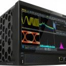
Rigol DS70504
Oscilloscopes
Product Description
The DS70000 series digital oscilloscope adopts RIGOL's chipset "Phoenix", delivering excellent performance with a maximum sample rate of 20 GSa/s, 5 GHz bandwidth. RIGOL's brand new UltraVison III technical platform guarantees the specifications to reach the advanced level in the industry, with the capture rate up to millions of waveforms per second, 2 Gpts memory depth, 8-16 bits adjustable resolution, and 10,000 FFTs/s.
In addition to the improved hardware specifications, the DS70000 series digital oscilloscope has a main 15.6-inch HD capacitive multi-touch screen equipped with electronically controlled one-button screen inclination for signal visualization, analysis, and results; a secondary 3.5-inch small screen with a customized function and shortcut menu display; and other user-friendly designs, bringing users an extraordinary human-machine interface experience.
4 channel oscilloscope with 5 GHz bandwidth, 20 GSa/s sample rate, up to 2 Gpts memory depth and a 39.6 cm multi-touch flip screen 1920×1080 pixel. Upgradable to a realtime spectrum analyzer.
Features
DS70000
Channel
4 (1 EXT channel)
Bandwidth
3 GHz - 5 GHz
Sample rate
4 channel with each 10 GSa/s
(single channel 20 GSa/s)
Waveform capture rate
1.000.000 wfms/s
Memory depth
Standard: 500 Mpts Option: 2 Gpts (single-channel), 1 Gpts (half-channel / all-channel)
Vertical Resolution
(selectable) 8-16 bits
LCD Size and Type
15.6" HD capacitive multi-touch flip screen/gesture enabled operation and 3.5" user-defined keyboard control touch screen
Display Resolution
1920×1080, 480×320
DS70000
Bandwidth
Channel
Real-time spectrum analyzer
Protocol analyzer
DS70304
3 GHz
4
Option
Option
DS70504
5 GHz (500MHz (1 MΩ, -3 dB))
4
Option
Option
You will find the specifications of the DS70000 series Click Here
High resolution up to 16 bits
The new high resolution capability allows users to set the desired number of bits (up to 16) for the measurement and then reports the available bandwidth. This removes signal noise that can obscure important test results
Up to 1.000.000 wfm/s waveform update rate
RIGOL's brand new UltraVison III technical platform guarantees the specifications to reach the advanced level in the industry, with the capture rate up to 1.000.000 wfm/s.
Photoelectric encoder
The photoelectric encoder operating knob guarantees more than 100.000 times of pressing operation and 1 million times of rotation operation, greatly improving the service life of the knob. With photoelectric encoders, you no longer have to worry about wear, ensuring reliable operation throughout the life of the instrument.
Multiple external interfaces
The Rigol DS70504 provides a variety of external interfaces that improve usability and data access including USB 3.0 Host andd Device, LAN (LXI), HDMI, AUX OUT, 10 MHz IN, 10 MHz Out and GPIB (option) via the USB-GPIB adaptor. For remote control over LAN, the DS70000 includes complete web control with web-based screen recording, a SCPI command interface, and ftp access to files stored on the instrument. The HDMI outputs supports use of an external monitor or video display.
Multi-window-support
The main display is a 39.6 cm (15.6") capacitive high-definition touch screen with one button electric tilt. Multi-pane windowing supports a variety of simultaneous analysis tools, making it easier to view signals, measurements, and results. Meanwhile, the secondary 13.5 cm (3,5") touch screen separates menues and functions from signals and analysis with a customized function and shortcut menu.
Eye diagram
Based on the excellent bandwidth and sample rate, the Rigol DS70504 oscilloscope provides the real-time eye plot and measurement with the clock recovery function, which can be applied to protocol conformance analysis. After the DS70000-JITTER option has been purchased and activated, DS70000 series supports the eye measurement for all the analog channels, and also provides measurement for several parameters of the eye diagram: eye height, eye width, eye amplitude, crossing percentage, and Q Factor. It also supports various clock recovery methods, such as Constant (automatic, semi-automatic, and manual), First-order PLL, Second-order PLL, and Explicit, to meet the demands of customers for different application scenarios.
Jitter
The Rigol DS70504 provides flexible and convenient jitter measurement and analysis. After purchasing and activating the DS70000-JITTER option, you can accurately and quickly make deterministic jitter measurements for serial clock signals or parallel bus signals.
Support various clock recovery methods, including:
Constant: Fully automatic, semi automatic, and manual
First-order PLL
Second-order PLL
Explicit
Electronic Label
The product model and its main parameters are displayed on the electronic label, sustaining its contents up to 20 years even at power-off state. The parameters will be updated automatically after upgrade to keep the information displayed on the electronic label consistent with that of the current instrument. Users can get the updated product information in a timely manner through the electronic label.
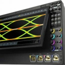
Rigol DS70304
Oscilloscopes
Product Description
The DS70000 series digital oscilloscope adopts RIGOL's chipset "Phoenix", delivering excellent performance with a maximum sample rate of 20 GSa/s, 5 GHz bandwidth. RIGOL's brand new UltraVison III technical platform guarantees the specifications to reach the advanced level in the industry, with the capture rate up to millions of waveforms per second, 2 Gpts memory depth, 8-16 bits adjustable resolution, and 10,000 FFTs/s.
Real-time spectrumanalyzer (option)
Eye diagram and jitter analysis (option)
Main 39.6 cm (15.6") HD capacitive multi-touch screen
Secondary 13.5 cm (3,5") touch screen separates menus and functions
7 GHz high-end active differential probe PVA8700 (option)
4 channel oscilloscope with 3 GHz bandwidth, 20 GSa/s sample rate, up to 2 Gpts memory depth and a 39.6 cm multi-touch flip screen 1920×1080 pixel. Upgradable to a realtime spectrum analyzer.
Features
DS70000
Channel
4 (1 EXT channel)
Bandwidth
3 GHz - 5 GHz
Sample rate
4 channel with each 10 GSa/s
(single channel 20 GSa/s)
Waveform capture rate
1.000.000 wfms/s
Memory depth
Standard: 500 Mpts Option: 2 Gpts (single-channel), 1 Gpts (half-channel / all-channel)
Vertical Resolution
(selectable) 8-16 bits
LCD Size and Type
15.6" HD capacitive multi-touch flip screen/gesture enabled operation and 3.5" user-defined keyboard control touch screen
Display Resolution
1920×1080, 480×320
DS70000
Bandwidth
Channel
Real-time spectrum analyzer
Protocol analyzer
DS70304
3 GHz
4
Option
Option
DS70504
5 GHz (500MHz (1 MΩ, -3 dB))
4
Option
Option
You will find the specifications of the DS70000 series Click Here .
High resolution up to 16 bits
The new high resolution capability allows users to set the desired number of bits (up to 16) for the measurement and then reports the available bandwidth. This removes signal noise that can obscure important test results
Up to 1.000.000 wfm/s waveform update rate
RIGOL's brand new UltraVison III technical platform guarantees the specifications to reach the advanced level in the industry, with the capture rate up to 1.000.000 wfm/s.
Photoelectric encoder
The photoelectric encoder operating knob guarantees more than 100.000 times of pressing operation and 1 million times of rotation operation, greatly improving the service life of the knob. With photoelectric encoders, you no longer have to worry about wear, ensuring reliable operation throughout the life of the instrument.
Multiple external interfaces
The Rigol DS70304 provides a variety of external interfaces that improve usability and data access including USB 3.0 Host andd Device, LAN (LXI), HDMI, AUX OUT, 10 MHz IN, 10 MHz Out and GPIB (option) via the USB-GPIB adaptor. For remote control over LAN, the DS70000 includes complete web control with web-based screen recording, a SCPI command interface, and ftp access to files stored on the instrument. The HDMI outputs supports use of an external monitor or video display.
Multi-window-support
The main display is a 39.6 cm (15.6") capacitive high-definition touch screen with one button electric tilt. Multi-pane windowing supports a variety of simultaneous analysis tools, making it easier to view signals, measurements, and results. Meanwhile, the secondary 13.5 cm (3,5") touch screen separates menues and functions from signals and analysis with a customized function and shortcut menu.
Eye diagram
Based on the excellent bandwidth and sample rate, the Rigol DS70304 oscilloscope provides the real-time eye plot and measurement with the clock recovery function, which can be applied to protocol conformance analysis. After the DS70000-JITTER option has been purchased and activated, DS70000 series supports the eye measurement for all the analog channels, and also provides measurement for several parameters of the eye diagram: eye height, eye width, eye amplitude, crossing percentage, and Q Factor. It also supports various clock recovery methods, such as Constant (automatic, semi-automatic, and manual), First-order PLL, Second-order PLL, and Explicit, to meet the demands of customers for different application scenarios.
Jitter
The Rigol DS70304 provides flexible and convenient jitter measurement and analysis. After purchasing and activating the DS70000-JITTER option, you can accurately and quickly make deterministic jitter measurements for serial clock signals or parallel bus signals.
Support various clock recovery methods, including:
Constant: Fully automatic, semi automatic, and manual
First-order PLL
Second-order PLL
Explicit
Electronic Label
The product model and its main parameters are displayed on the electronic label, sustaining its contents up to 20 years even at power-off state. The parameters will be updated automatically after upgrade to keep the information displayed on the electronic label consistent with that of the current instrument. Users can get the updated product information in a timely manner through the electronic label.
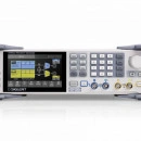
Siglent SDG7000A Arbitrary Waveform Generator
Function Generator
Product Description
SIGLENT’s SDG7000A is a family of dual-channel Arbitrary Waveform Generators that feature up to 1 GHz bandwidth, a maximum sample rate of 5 GSa/s, and 14-bit vertical resolution. It can generate arbitrary waveforms point by point with a maximum 2.5 GSa/s sample rate and vector signals with a maximum of 500 MSa/s. It also has the ability to generate a variety of signals such as continuous wave, Pulse, Noise, PRBS patterns, and a 16-bit digital bus. It supports the generation of complex signals such as modulation, sweeping, bursting, and dual-channel copying/coupling/tracking and superposition. The outputs are user selectable for differential or single-ended connections and support a maximum output range of ± 24 V. The instrument can ensure a large amplitude under high-frequency which eliminates an external power amplifier in some applications and addresses a wider range of requirements.
Key Features
Generates low jitter pulses with 1 ns minimum pulsewidth and 500 ps minimum edge
Up to 1 GHz bandwidth and White Gaussian Noise with adjustable bandwidth
PRBS up to 312.5 Mbps
LVTTL and LVDS Digital bus options for digital signal sourcing up to 1 Gbps
Includes popular analog/digital modulation types, sweeping and bursting functions
Enhanced dual-channel operation functions: inter-channel tracking, coupling, and copying
Dual-channel superposition function
Mutual modulation between channels
The 24 Vpp analog output is superimposed with ± 12 Vdc offset to provide a maximum output range of ± 24 V (48 V)
High precision Frequency Counter
5-inch capacitive touch screen with a resolution of 800×480
External mouse and keyboard operation
WebServer to control the instruments remotely without downloading software
Includes 10 MHz In, 10 MHz Out, Trigger In/Out, and Marker sync connections
Full SCPI command manual for easy integration into test systems
Click Here for Specifications
Max Output Frequency
Max Sampling Rate
Vertical Resolution
Waveform Length
Channels
SDG7102A
1 GHz
5G Sa/s
14-bit
512Mpts
2 Differential/Single-ended
SDG7052
500MHz
5G Sa/s
14-bit
512Mpts
2 Differential/Single-ended
SDG7032
350MHz
5G Sa/s
14-bit
512Mpts
2 Differential/Single-ended
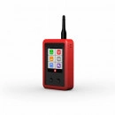
BLOOMICE 2G/3G/4G signal tester / analyser, (BM-03039R)
Spectrum Analyzer
Product Description
User friendly, hand held device perfect for use in ‘on-site’ antenna placement measurement
Features:
The Bloomice 2G/3G/4G signal tester / analyser is a user friendly, hand held device perfect for use in ‘on-site’ antenna placement measurement. It is encased within a protective rubber suit and is water and dust resistant to IP65. An integrated lithium-ion battery provides power for up to 12 hours of continuous usage. It is ideal for use in determining optimal antenna positioning with Alarm Signalling Systems, Vending Machines, Parking Hardware, Vehicle Tracking & Telematics, Network Routers and Smart Meters.
Specifications Download : Click Here
Rigol DP831A
Power Supplies
Product Description
The Rigol DP831A is a very high quality programmable laboratory power supply with three switchable outputs (+8 V/5 A, +30 V/2 A and -30 V/2 A) and a maximum power output of 160 W.
Like all Rigol devices, the power supply features a very well constructed and easy to use interface, which also offers comprehensive ease-of-use functions, such as programmable voltage curves. The menu has an intuitive structure.
The Rigol DP831A features a relative large (8.9 cm / 3.5") and easy to read TFT color display. In addition to the normal digital displays for voltage, current, and power, these values can also be displayed as signal curves. A timer control can be used to set the output signal to different values in up to 2048 steps.
Quick comparision
DP811 / DP811A
DP821 / DP821A
DP831 / DP831A
DP832 / DP832A
Voltage / Current CH1
0 - +20 V / 0 - 10 A
oder
0 - +40 V / 0 - 5 A
0 - +60 V / 0 - 1 A
0 - +8 V / 0 - 5 A
0 - +30 V / 0 - 3 A
Voltage / Current CH2
0 - +8 V / 0 - 10 A
0 - +30 V / 0 - 2 A
0 - +30 V / 0 - 3 A
Voltage / Current CH3
0 - -30 V / 0 - 2 A
0 - +5 V / 0 - 3 A
I/O Ports
USB device, USB Host
A-Models
Basic Models
Voltage Resolution
1 mV
10 mV (1 mV with High-Resolution Option)
LAN, RS232 and Digital IO Ports
Included
Option
Online Monitoring & Analysis Function
Included
Option
Display
3.5" (8.9 cm) Color-TFT
3.5" (8.9 cm) Monochrome TFT
Special Features
Clearly Arranged Display
All important data such as voltage, current, power, and limit values can easily be displayed on the display with a diagonal size of 8.9 cm (3.5") and a resolution of 320x240 pixels.
Output Monitoring
The monitor can monitor the current output state of the instrument. When the user-defined monitor condition is met, the instrument executes the corresponding operation according to the setting in "Stop Mode", like showing a warning, shut off the output or produce a beep sound.
Display Signal Curves
Changes in the measurement values and settings can be presented very well and in real time using the integrated signal curve display. This makes it possible to detect things like current draw peaks, for example when the current limit is adjusted.
Programmable Timer
The voltage and current settings can be changed automatically with a timer control. Up to 100 settings can be stored for this purpose, and then activated one after another for variable intervals (specified in seconds).
Output Analysis
The analyzer can analyze the file recorded and provides the analysis results, including the number of groups, median, mode as well as the average, VAR, range, minimum, maximum and mean deviation of the voltage, current or power of different channel.
Trigger Output
The rear panel of DP800A provides a digital I/O interface (as shown below) which supports trigger input and trigger output. The 4 data lines are mutually independent and can be used as trigger input line or trigger output line separately.
Excellent connectivity and remote control via SCPI / LabView
The Rigol DP831A can be controlled remotely with SCPI commands through a variety of interfaces. The following interfaces are available:
USB
LAN
GPIB (optional)
Control of the device can be integrated into your own applications, or by using LabView via these interfaces.
Download Specifications :
Click Here
FiberFox MINI 60A One Click Cleaver
Fibre Optic Cleavers
Product Description
Single & ribbon fiber cleaver
One click cleaving
265g / 105'108'56mm(with Auto chip collector), 105'90'56mm(with trash bin)
80"125um
Single Fiber:10-20mm / Ribbon fiber: 10mm
Single Fiber: 250um, 900um, 3.0mm fiber cable and indoor cable / Ribbon fiber: 2 to 12 ribbon fiber cable
Single Fiber: 0.3°-0.9° (Ave.0.5°) / Ribbon Fiber: 0.3°-1.2° (Ave.0.5°)
Operation Method: One Click Cleaving
Applicable Fiber:
Single fiber (250μm, 900μm, 2~3ф, indoor cable)
Ribbon fiber (1~12ch fiber)
Coating Diameter: Max. 3mm
Cleave Length:
Single fiber: 10~20mm
Ribbon fiber: 10mm
Cleave Angle: Single Fiber:0.3°~ 0.9° (Ave.0.5°)
Ribbon Fiber:0.3°~ 1.2°
Blade Life Span: 60,000 times
Size: 105x108x56mm(with Auto chip collector)
Weight: 260g
Operation Condition: Temperature:-10~50℃
Humidity:0~95%RH
Storage Condition: Temperature:-40~80℃
Humidity:0~95%RH
Blade Rotation: O (Manual)
Cleaving Counter: O
Auto Chip collector: O
Built-in Tool kit: O
Download Brochure:
Click here : Mini60A
Click Here : Spec sheet
Siglent SSA3075X Plus (9 kHz to 7.5 GHz)
Siglent Spectrum Analyzers
Product Description
Spectrum analyzer from 9 kHz to 7.5 GHz with a 25.7 cm LCD touch-display (1024x600 pixel). Incl. Preamplifier and Tracking Generator.
The Siglent SSA3000X is a compact and light weight Spectrum Analyzer with premium performance for portable applications. The use of digital IF (intermediate frequency) technology guarantees reliability and performance to meet the most demanding RF applications.
The very large display (25.65 cm / 10.1") of the Siglent SSA3021X Spectrum Analyzer provides a resolution of 1024x600 pixels. The SSA3000X Plus has a (25.65 cm / 10.1") Mutli Touch Display with a resolution of 1024x600 pixels.
Both Models allowing a very good overview of all its comfortable functions like measurements, marker and peak table, auto tune and coupling. These functions enable the analyzer to acquire signals and match parameters automatically, compared to the manual process necessary with a traditional analyzer.
The Siglent Spectrum Analyzers have a sophisticated and easy to use user interface offering multiple functions for all tasks. The menu navigation is very intuitive and all functions and parameters are easy to locate thanks to the graphical interface.
Models
SSA3021X
Obsolete
SSA3032X
Obsolete
SSA3015X Plus
SSA3021X Plus
SSA3032X Plus
SSA3075X Plus
Max. Bandwidth
2.1 GHz
3.2 GHz
1.5 GHz
2.1 GHz
3.2 GHz
7.5 GHz
Preamplifier
Tracking Generator
EMI Filter
Option
Option
Option
Option
Option
Option
AMK CHP/ACPR/TOI/OBW/Monitor
Option
Option
Option
Option
Option
Option
AMA AM/FM
n/a
n/a
Option
Option
Option
Option
DMA ASK/FSK/PSK/QAM
n/a
n/a
Option
Option
Option
Option
Touch Screen
n/a
n/a
Resolution bandwidth (RBW)
1 Hz ~ 1 MHz, in 1-3-10 sequence
1 Hz ~ 1 MHz, in 1-3-10 sequence
1 Hz ~ 1 MHz, in 1-3-10 sequence
1 Hz ~ 1 MHz, in 1-3-10 sequence
1 Hz ~ 1 MHz, in 1-3-10 sequence
1 Hz ~ 1 MHz, in 1-3-10 sequence
Display average noise level (DANL), min.
-161 dBm/Hz, Normalize to 1 Hz (typ.)
-161 dBm/Hz, Normalize to 1 Hz (typ.)
-156 dBm/Hz
-161 dBm/Hz
-161 dBm/Hz
-165 dBm/Hz
You will find the specifications of the SSA3000X Plus series: Click Here
Support four traces and cursors independently
1 Hz Minimum Resolution Bandwidth (RBW)
AM Signal Demodulation at the zero span
Phase noise -98 dBc/Hz@1 GHz, offset 10 kHz
-151 dBm Displayed Average Noise Level (RBW=1 Hz)
Advanced power measurement (Option)
Design Features
Characteristic curve of the Return Loss (Option)
EMI filter, Quasi-Peak detector following CISPR 16 (Option)
Siglent SSA3032X Plus (9 kHz to 3.2 GHz)
Siglent Spectrum Analyzers
Product Description
Spectrum analyzer from 9 kHz to 3.2 GHz with a 25.7 cm LCD touch-display (1024x600 pixel). Incl. Preamplifier and Tracking Generator.
The Siglent SSA3000X is a compact and light weight Spectrum Analyzer with premium performance for portable applications. The use of digital IF (intermediate frequency) technology guarantees reliability and performance to meet the most demanding RF applications.
The very large display (25.65 cm / 10.1") of the Siglent SSA3021X Spectrum Analyzer provides a resolution of 1024x600 pixels. The SSA3000X Plus has a (25.65 cm / 10.1") Mutli Touch Display with a resolution of 1024x600 pixels.
Both Models allowing a very good overview of all its comfortable functions like measurements, marker and peak table, auto tune and coupling. These functions enable the analyzer to acquire signals and match parameters automatically, compared to the manual process necessary with a traditional analyzer.
The Siglent Spectrum Analyzers have a sophisticated and easy to use user interface offering multiple functions for all tasks. The menu navigation is very intuitive and all functions and parameters are easy to locate thanks to the graphical interface.
Models
SSA3021X
Obsolete
SSA3032X
Obsolete
SSA3015X Plus
SSA3021X Plus
SSA3032X Plus
SSA3075X Plus
Max. Bandwidth
2.1 GHz
3.2 GHz
1.5 GHz
2.1 GHz
3.2 GHz
7.5 GHz
Preamplifier
Tracking Generator
EMI Filter
Option
Option
Option
Option
Option
Option
AMK CHP/ACPR/TOI/OBW/Monitor
Option
Option
Option
Option
Option
Option
AMA AM/FM
n/a
n/a
Option
Option
Option
Option
DMA ASK/FSK/PSK/QAM
n/a
n/a
Option
Option
Option
Option
Touch Screen
n/a
n/a
Resolution bandwidth (RBW)
1 Hz ~ 1 MHz, in 1-3-10 sequence
1 Hz ~ 1 MHz, in 1-3-10 sequence
1 Hz ~ 1 MHz, in 1-3-10 sequence
1 Hz ~ 1 MHz, in 1-3-10 sequence
1 Hz ~ 1 MHz, in 1-3-10 sequence
1 Hz ~ 1 MHz, in 1-3-10 sequence
Display average noise level (DANL), min.
-161 dBm/Hz, Normalize to 1 Hz (typ.)
-161 dBm/Hz, Normalize to 1 Hz (typ.)
-156 dBm/Hz
-161 dBm/Hz
-161 dBm/Hz
-165 dBm/Hz
You will find the specifications of the SSA3000X Plus series Click Here
Support four traces and cursors independently
1 Hz Minimum Resolution Bandwidth (RBW)
AM Signal Demodulation at the zero span
Phase noise -98 dBc/Hz@1 GHz, offset 10 kHz
-151 dBm Displayed Average Noise Level (RBW=1 Hz)
Advanced power measurement (Option)
Design Features
Characteristic curve of the Return Loss (Option)
EMI filter, Quasi-Peak detector following CISPR 16 (Option)
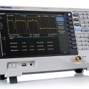
Siglent SSA3021X Plus (9 kHz to 2.1 GHz)
Siglent Spectrum Analyzers
Product Description
Spectrum analyzer from 9 kHz to 2.1 GHz and with a 25.7 cm LCD touch-display (1024x600 pixel). Incl. Preamplifier and Tracking Generator.
The Siglent SSA3000X is a compact and light weight Spectrum Analyzer with premium performance for portable applications. The use of digital IF (intermediate frequency) technology guarantees reliability and performance to meet the most demanding RF applications.
The very large display (25.65 cm / 10.1") of the Siglent SSA3021X Spectrum Analyzer provides a resolution of 1024x600 pixels. The SSA3000X Plus has a (25.65 cm / 10.1") Mutli Touch Display with a resolution of 1024x600 pixels.
Both Models allowing a very good overview of all its comfortable functions like measurements, marker and peak table, auto tune and coupling. These functions enable the analyzer to acquire signals and match parameters automatically, compared to the manual process necessary with a traditional analyzer.
The Siglent Spectrum Analyzers have a sophisticated and easy to use user interface offering multiple functions for all tasks. The menu navigation is very intuitive and all functions and parameters are easy to locate thanks to the graphical interface.
Models
SSA3021X
Obsolete
SSA3032X
Obsolete
SSA3015X Plus
SSA3021X Plus
SSA3032X Plus
SSA3075X Plus
Max. Bandwidth
2.1 GHz
3.2 GHz
1.5 GHz
2.1 GHz
3.2 GHz
7.5 GHz
Preamplifier
Tracking Generator
EMI Filter
Option
Option
Option
Option
Option
Option
AMK CHP/ACPR/TOI/OBW/Monitor
Option
Option
Option
Option
Option
Option
AMA AM/FM
n/a
n/a
Option
Option
Option
Option
DMA ASK/FSK/PSK/QAM
n/a
n/a
Option
Option
Option
Option
Touch Screen
n/a
n/a
Resolution bandwidth (RBW)
1 Hz ~ 1 MHz, in 1-3-10 sequence
1 Hz ~ 1 MHz, in 1-3-10 sequence
1 Hz ~ 1 MHz, in 1-3-10 sequence
1 Hz ~ 1 MHz, in 1-3-10 sequence
1 Hz ~ 1 MHz, in 1-3-10 sequence
1 Hz ~ 1 MHz, in 1-3-10 sequence
Display average noise level (DANL), min.
-161 dBm/Hz, Normalize to 1 Hz (typ.)
-161 dBm/Hz, Normalize to 1 Hz (typ.)
-156 dBm/Hz
-161 dBm/Hz
-161 dBm/Hz
-165 dBm/Hz
You will find the specifications of the SSA3000X Plus series: Click here
Support four traces and cursors independently
1 Hz Minimum Resolution Bandwidth (RBW)
AM Signal Demodulation at the zero span
Phase noise -98 dBc/Hz@1 GHz, offset 10 kHz
-151 dBm Displayed Average Noise Level (RBW=1 Hz)
Advanced power measurement (Option)
Design Features
Characteristic curve of the Return Loss (Option)
EMI filter, Quasi-Peak detector following CISPR 16 (Option)
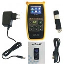
Satlink WS-6933 Satellite Signal Finder 2.1 LCD DVB-S2
Satellite Finder
Product Description
Specification:2.1 Inch LCD Screen DisplayInput Frequency 950~2150MHzInput Level -65~ -25dBmInput Impedance 75 ohmMeasurement Type : Signal Strength, Quality, PowerSound for Locking SignalSupport DISEQC 1.0 /1.1 and 22khz ToneLNB Power Supply : 18/13V(IMax 300mA)Beep Integrated7.4V/800mAh Lion Battery IncludedMax Operating Time : 3 hours12V/1.2A DC Adapter
Rear Flashlight FunctionUSB Port For Software Upgrades
Package Includes:1 x Satlink ws-6933 satellite finder1 x Silicone Case1 x USB Cable1 x Power Adapter
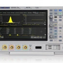
Siglent SDS2204X Plus 200MHz 4 Channel
Siglent Oscilloscopes
Product Description
The Siglent SDS2204X Plus Digital Storage Oscilloscopes are available in bandwidths of 100 MHz - 500 MHz, have a maximum sample rate of 2 GSa/s, maximum record length of 200 Mpts, and display up to 4 analog channels + 16 digital channels mixed signal analysis ability.
The Siglent SDS2204X Plus employs Siglent’s SPO technology with a maximum waveform capture rate of up to 120,000 wfm/ s (normal mode, up to 500,000 wfm/s in Sequence mode), 256-level intensity grading display function plus a color temperature display mode. It also employs an innovative digital trigger system with high sensitivity and low jitter.
The trigger system supports multiple powerful triggering modes including serial bus triggering. History waveform recording, Sequence acquisition, Search and Navigate functions allow for extended waveform records to be captured, stored, and analyzed.
An impressive array of measurement and math capabilities, options for a 50 MHz arbitrary waveform generator, as well as serial decoding are also features of the Siglent SDS2204X Plus.
The large 10.1’’ display capacitive touch screen supports multi-touch gestures, with the addition of user-friendly one-button design for most commonly used functions, can greatly improve the operation efficiency of the Siglent SDS2204X Plus.
Features
SDS2000X Plus
Channel
2 - 4
Bandwidth
100 MHz - 500 MHz
Sample rate
2 channel with each 2 GSa/s
4 channel with each 1 GSa/s
Waveform capture rate
480.000 wfms/s
Memory depth
2 channel with each 200 Mpts
4 channel with each 100 Mpts
SDS2000X Plus
Bandwidth
Channel
Logic Analyzer
Waveform generator
SDS2102X Plus
100 MHz (upgradable to 350 MHz)
2
Option
Option
SDS2104X Plus
100 MHz (upgradable to 200 MHz)
4
Option
Option
SDS2204X Plus
200 MHz (upgradable to 350 MHz)
4
Option
Option
SDS2354X Plus
350 MHz (upgradable to 500 MHz)
4
Option
Option
Download Specifications:
Siglent SDS2204X Plus
Special Features
Low noise floor
Low noise floor: Only 80 µV rms at 500 MHz bandwidth.
Up to 120.000 wfm/s waveform update rate
With a waveform update rate of up to 120.000 wfm/s, the Siglent SDS2104X Plus can easily capture low-probability events. In Sequence mode the waveform capture rate can reach 500.000 wfm/s.
Record length of up to 200 Mpts/ch
Utilizing a hardware-based Zoom technique and record length up to 200 Mpts, users can select a slower timebase without compromising the sample rate and then quickly zoom in to focus on the area of interest.
10-bit mode
10-bit mode combined with Zoom shows you more details and less noise on the waveform.
Trigger zone
Trigger Zone is available for advanced triggering.
Measurement for all relevant parameters and parameter statistics
Parameter measurements includes 4 categories: vertical, horizontal, miscellaneous and channel delay providing a total of 50+ different types of measurements. Measurements can be performend within a specified gate period. Measurements on math, reference and history frames are supported.
Advanced math functions
Hardware accelerated FFT up to 2 Mpts. This provides high frequency resolution with fast refresh rate. The FFT function also supports variety of window functions so that it can adapt to different spectrum measurement needs. three modes (normal, average and max hold) can satisfy different requirements for observing the power spectrum. Auto peak detection and markers are supported.
Sequence Mode
Segmented memory collection will store the waveform into multiple memory segments (up to 90.000) and each segment will store a triggered waveform together with the dead time information. The interval between segments can be as small as 2 µs. All segments can be played back at an arbitrary frame rate using the history function.
Search and navigate
The Siglent SDS2104X Plus can find events within a record and history based on user specified trigger conditions. Navigate browses through events flagged by search, plays back history frames or continuosly moves the delay position on long records (useful in zoom view).
Serial bus decode
In addition to the decoder lanes correlated to the waveform, bus protocol information can be displayed in tabular form. I2C, SPI, UART, CAN, LIN, CAN FD, FlexRay, I2S and MIL-STD-1553B are supported.
Hardware-based high speed mask test function
The Siglent SDS2104X Plus utilizes a hardware-based mask test function, performing up to 80.000 Pass / Fail decisions each second. It is easy to generate user defined test templates which the signal trace can be continuously compared to. The failed frames can be automatically stored as history frames or screen shots, making it suitable for long term signal monitoring or automated production line testing.
Power analysis
The power analysis option provides a full suite of power measurements and analysis, thus improving the efficiency of measurement in switching power supplies and power device designs.
50 MHz built-in waveform generator
The built-in waveform generator can output waveforms with up to 50 MHz frequency and +-3 V amplitude. Six basic waveforms together with multiple types of predefined waveforms and as user defined arbitrary waveforms are supported.
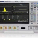
Siglent SDS2104X Plus 100MHz 4 Channel
Siglent Oscilloscopes
Product Description
The Siglent SDS2104X Plus Digital Storage Oscilloscopes are available in bandwidths of 100 MHz - 500 MHz, have a maximum sample rate of 2 GSa/s, maximum record length of 200 Mpts, and display up to 4 analog channels + 16 digital channels mixed signal analysis ability.
The Siglent SDS2104X Plus employs Siglent’s SPO technology with a maximum waveform capture rate of up to 120,000 wfm/ s (normal mode, up to 500,000 wfm/s in Sequence mode), 256-level intensity grading display function plus a color temperature display mode. It also employs an innovative digital trigger system with high sensitivity and low jitter.
The trigger system supports multiple powerful triggering modes including serial bus triggering. History waveform recording, Sequence acquisition, Search and Navigate functions allow for extended waveform records to be captured, stored, and analyzed.
An impressive array of measurement and math capabilities, options for a 50 MHz arbitrary waveform generator, as well as serial decoding are also features of the Siglent SDS2104X Plus.
The large 10.1’’ display capacitive touch screen supports multi-touch gestures, with the addition of user-friendly one-button design for most commonly used functions, can greatly improve the operation efficiency of the Siglent SDS2104X Plus.
Features
SDS2000X Plus
Channel
2 - 4
Bandwidth
100 MHz - 500 MHz
Sample rate
2 channel with each 2 GSa/s
4 channel with each 1 GSa/s
Waveform capture rate
480.000 wfms/s
Memory depth
2 channel with each 200 Mpts
4 channel with each 100 Mpts
SDS2000X Plus
Bandwidth
Channel
Logic Analyzer
Waveform generator
SDS2102X Plus
100 MHz (upgradable to 350 MHz)
2
Option
Option
SDS2104X Plus
100 MHz (upgradable to 200 MHz)
4
Option
Option
SDS2204X Plus
200 MHz (upgradable to 350 MHz)
4
Option
Option
SDS2354X Plus
350 MHz (upgradable to 500 MHz)
4
Option
Option
Download Specifications :
Siglent SDS2104X Plus
Special Features
Low noise floor
Low noise floor: Only 80 µV rms at 500 MHz bandwidth.
Up to 120.000 wfm/s waveform update rate
With a waveform update rate of up to 120.000 wfm/s, the Siglent SDS2104X Plus can easily capture low-probability events. In Sequence mode the waveform capture rate can reach 500.000 wfm/s.
Record length of up to 200 Mpts/ch
Utilizing a hardware-based Zoom technique and record length up to 200 Mpts, users can select a slower timebase without compromising the sample rate and then quickly zoom in to focus on the area of interest.
10-bit mode
10-bit mode combined with Zoom shows you more details and less noise on the waveform.
Trigger zone
Trigger Zone is available for advanced triggering.
Measurement for all relevant parameters and parameter statistics
Parameter measurements includes 4 categories: vertical, horizontal, miscellaneous and channel delay providing a total of 50+ different types of measurements. Measurements can be performend within a specified gate period. Measurements on math, reference and history frames are supported.
Advanced math functions
Hardware accelerated FFT up to 2 Mpts. This provides high frequency resolution with fast refresh rate. The FFT function also supports variety of window functions so that it can adapt to different spectrum measurement needs. three modes (normal, average and max hold) can satisfy different requirements for observing the power spectrum. Auto peak detection and markers are supported.
Sequence Mode
Segmented memory collection will store the waveform into multiple memory segments (up to 90.000) and each segment will store a triggered waveform together with the dead time information. The interval between segments can be as small as 2 µs. All segments can be played back at an arbitrary frame rate using the history function.
Search and navigate
The Siglent SDS2104X Plus can find events within a record and history based on user specified trigger conditions. Navigate browses through events flagged by search, plays back history frames or continuosly moves the delay position on long records (useful in zoom view).
Serial bus decode
In addition to the decoder lanes correlated to the waveform, bus protocol information can be displayed in tabular form. I2C, SPI, UART, CAN, LIN, CAN FD, FlexRay, I2S and MIL-STD-1553B are supported.
Hardware-based high speed mask test function
The Siglent SDS2104X Plus utilizes a hardware-based mask test function, performing up to 80.000 Pass / Fail decisions each second. It is easy to generate user defined test templates which the signal trace can be continuously compared to. The failed frames can be automatically stored as history frames or screen shots, making it suitable for long term signal monitoring or automated production line testing.
Power analysis
The power analysis option provides a full suite of power measurements and analysis, thus improving the efficiency of measurement in switching power supplies and power device designs.
50 MHz built-in waveform generator
The built-in waveform generator can output waveforms with up to 50 MHz frequency and +-3 V amplitude. Six basic waveforms together with multiple types of predefined waveforms and as user defined arbitrary waveforms are supported.
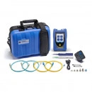
TREND FiberMASTER Quad OTDR (850/1300/1310/1550) R240-QIP
OTDRs
Product Description
Test, Troubleshoot and Certify cabling faster with the FiberMASTER OTDR.
The FiberMASTER OTDR is available in 4 options, Quad, multimode, singlemode and PON.
The OTDRs feature both high dynamic range and small dead zones providing the precision required for installation and troubleshooting alike. The software simplifies certification of cabling to meet TIA/ISO/IEC/IEEE requirements with simple pass/fail results. Additionally custom test parameters are easily set to accommodate any application.
OTDRs can be complicated to configure and achieve accurate results. FiberMASTER automates testing and steps you through the process as shown below.
For FTTx/FTTH applications the PON OTDR identifies split ratios for easy testing and troubleshooting of inactive and active networks. The 1625nm wavelength allows in-service testing of networks without interrupting existing subscribers.
Product Features
Why do I need a FiberMASTER?
It depends how important speed and accuracy are to you.
FiberMASTER – size, simplicity and value without compromise, made in the USA, tested in Germany.
The new FiberMASTER series of fiber optic testers will make it easier and faster to verify, troubleshoot and certify fiber optic cabling.The OTDR, PON OTDR, Power Meter and Light Source, and Inspection Probe will enable cable installers to get the dependable test results needed, while saving thousands of dollars.As one of the smallest OTDRs in the world you will find them easier to carry and operate while the ruggedised housing will protect your investment. The simplified setup options makes them easy to use, saving you time on training and reducing the likelihood of errors.
Our New York Research and Development centre of excellence has over 30 years experience designing OTDRs providing you with the most advanced, compact optical test systems available.
Download Specifications:
FibreMASTER Brochure
Kit Contents:
FiberMASTER Quad OTDR (850/1300/1310/1550) with SC connectors, Inspection port, Power meter, Power Adapter (1), USB Cable (1), Stylus (2), Carry Case (1), Hang. Strap (1), Cleaning Pen 1.25mm (1) and 2.5mm (1), MM 2m Cable LC-SC (1), MM 2m Cable SC-SC (1), SM 2m Cable LC-SC (1), SM 2m Cable SC-SC (1), Power Meter Connectors (LC,SC,FC,ST,1.25mm UNIV, 2.5mm UNIV), Quick Ref. Guide (1)
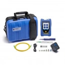
TREND FiberMASTER PON OTDR (1310/1550/1625nm) R240-PIP
OTDRs
Product Description
Test, Troubleshoot and Certify cabling faster with the FiberMASTER OTDR.
The FiberMASTER OTDR is available in 4 options, Quad, multimode, singlemode and PON.
The OTDRs feature both high dynamic range and small dead zones providing the precision required for installation and troubleshooting alike. The software simplifies certification of cabling to meet TIA/ISO/IEC/IEEE requirements with simple pass/fail results. Additionally custom test parameters are easily set to accommodate any application.
OTDRs can be complicated to configure and achieve accurate results. FiberMASTER automates testing and steps you through the process as shown below.
For FTTx/FTTH applications the PON OTDR identifies split ratios for easy testing and troubleshooting of inactive and active networks. The 1625nm wavelength allows in-service testing of networks without interrupting existing subscribers.
Product Features
Why do I need a FiberMASTER?
It depends how important speed and accuracy are to you.
FiberMASTER – size, simplicity and value without compromise, made in the USA, tested in Germany.
The new FiberMASTER series of fiber optic testers will make it easier and faster to verify, troubleshoot and certify fiber optic cabling.The OTDR, PON OTDR, Power Meter and Light Source, and Inspection Probe will enable cable installers to get the dependable test results needed, while saving thousands of dollars.As one of the smallest OTDRs in the world you will find them easier to carry and operate while the ruggedised housing will protect your investment. The simplified setup options makes them easy to use, saving you time on training and reducing the likelihood of errors.
Our New York Research and Development centre of excellence has over 30 years experience designing OTDRs providing you with the most advanced, compact optical test systems available.
Download Specifications:
FibreMASTER Brochure
Kit Contents:
FiberMASTER PON OTDR (1310/1550/1625) with SC-APC connectors, Inspection port, Power meter, Power Adapter (1), USB Cable (1), Stylus (2), Carry Case (1), Hang. Strap (1), Cleaning Pen 2.5mm (1), SM 2m APC Cable SC-SC, Power Meter Connectors (LC,SC,FC,ST,1.25mm UNIV, 2.5mm UNIV), Quick Ref. Guide (1)
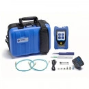
TREND FiberMASTER Multimode OTDR (850/1300nm) R240-MIPV
OTDRs
Product Description
Test, Troubleshoot and Certify cabling faster with the FiberMASTER OTDR.
The FiberMASTER OTDR is available in 4 options, Quad, multimode, singlemode and PON.
The OTDRs feature both high dynamic range and small dead zones providing the precision required for installation and troubleshooting alike. The software simplifies certification of cabling to meet TIA/ISO/IEC/IEEE requirements with simple pass/fail results. Additionally custom test parameters are easily set to accommodate any application.
OTDRs can be complicated to configure and achieve accurate results. FiberMASTER automates testing and steps you through the process as shown below.
For FTTx/FTTH applications the PON OTDR identifies split ratios for easy testing and troubleshooting of inactive and active networks. The 1625nm wavelength allows in-service testing of networks without interrupting existing subscribers.
Product features
Why do I need a FiberMASTER?
It depends how important speed and accuracy are to you.
FiberMASTER – size, simplicity and value without compromise, made in the USA, tested in Germany.
The new FiberMASTER series of fiber optic testers will make it easier and faster to verify, troubleshoot and certify fiber optic cabling.The OTDR, PON OTDR, Power Meter and Light Source, and Inspection Probe will enable cable installers to get the dependable test results needed, while saving thousands of dollars.As one of the smallest OTDRs in the world you will find them easier to carry and operate while the ruggedised housing will protect your investment. The simplified setup options makes them easy to use, saving you time on training and reducing the likelihood of errors.
Our New York Research and Development centre of excellence has over 30 years experience designing OTDRs providing you with the most advanced, compact optical test systems available.
Download Specifications:
FibreMASTER Brochure
Kit Contents:
FiberMASTER Multimode OTDR (850/1300) with SC connector, Inspection port, Power meter, Visual Fault Locator, Power Adapter (1), USB Cable (1), Stylus (2), Carry Case (1), Hang. Strap (1), Cleaning Pen 1.25mm (1) and 2.5mm (1), MM 2m Cable LC-SC (1), MM 2m Cable SC-SC (1), Power Meter Connectors (LC,SC,FC,ST,1.25mm UNIV, 2.5mm UNIV), Quick Ref. Guide (1)
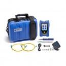
TREND FiberMASTER Single-mode OTDR (1310/1550nm)R240-SIPV
OTDRs
Product Description
Test, Troubleshoot and Certify cabling faster with the FiberMASTER OTDR.
The FiberMASTER OTDR is available in 4 options, Quad, multimode, singlemode and PON.
The OTDRs feature both high dynamic range and small dead zones providing the precision required for installation and troubleshooting alike. The software simplifies certification of cabling to meet TIA/ISO/IEC/IEEE requirements with simple pass/fail results. Additionally custom test parameters are easily set to accommodate any application.
OTDRs can be complicated to configure and achieve accurate results. FiberMASTER automates testing and steps you through the process as shown below.
For FTTx/FTTH applications the PON OTDR identifies split ratios for easy testing and troubleshooting of inactive and active networks. The 1625nm wavelength allows in-service testing of networks without interrupting existing subscribers.
Product features
Why do I need a FiberMASTER?
It depends how important speed and accuracy are to you.
FiberMASTER – size, simplicity and value without compromise, made in the USA, tested in Germany.
The new FiberMASTER series of fiber optic testers will make it easier and faster to verify, troubleshoot and certify fiber optic cabling.The OTDR, PON OTDR, Power Meter and Light Source, and Inspection Probe will enable cable installers to get the dependable test results needed, while saving thousands of dollars.As one of the smallest OTDRs in the world you will find them easier to carry and operate while the ruggedised housing will protect your investment. The simplified setup options makes them easy to use, saving you time on training and reducing the likelihood of errors.
Our New York Research and Development centre of excellence has over 30 years experience designing OTDRs providing you with the most advanced, compact optical test systems available.
Download Specifications:
FibreMASTER Brochure
Kit Contents :
FiberMASTER Single-mode OTDR (1310/1550) with SC connector, Inspection port, Power meter, Visual Fault Locator, Power Adapter (1), USB Cable (1), Stylus (2), Carry Case (1), Hang. Strap (1), Cleaning Pen 1.25mm (1) and 2.5mm (1), SM 2m Cable LC-SC (1), SM 2m Cable SC-SC (1), Power Meter Connectors (LC,SC,FC,ST,1.25mm UNIV, 2.5mm UNIV), Quick Ref. Guide (1)
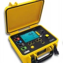
C.A 6471 Earth Tester
Ground Resistance Testers
Product Description
Earth tester offering selective earth, soil resistivity, earth coupling and continuity measurementsErgonomic, comprehensive and accurate, the C.A 6471 offers direct access to all the measurements on the front panel by means of a rotary switch. Compact because it has been designed for on-site use, the C.A 6471 is rugged and leakproof. To simplify connection, the 4 terminals for connecting the stakes are colour-coded to help identify them. The C.A 6471 includes a large backlit LCD screen and a battery which is rechargeable with an external charger connected to the mains or to a vehicle cigarette lighter. It is also equipped with a function for direct, ordered storage of the measurement results. A USB communication output can be used to export the data onto a PC in order to process them with the Ground Tester Transfer software. SpecificationsThe C.A 6471 guarantees the reliability of measurements carried out by:
traditional stake-based methods
self-diagnosis when each measurement starts, so that any faults liable to affect the measurements (bad connections or presence of disturbance signals) are indicated
extensive measurement ranges: 0.001 Ω to 100 kΩ
adjustment of the measurement frequency between 41 Hz and 512 Hz (3P & 4P measurements)
The C.A 6471 is equipped with advanced expert calculation functions:
for earth coupling measurements, simply perform the 3 successive measurements required and the tester then calculates the coupling coefficient automatically
for soil resistivity measurements, simply program the distances used for the measurement and the instrument automatically calculates r using the Wenner or Schlumberger methods.
Other specifications:
Power supply: NiMh rechargeable battery with external charger
IP53 protection
Compliant with IEC 61557 -1 -4 -5
Safety: IEC 61010 50V CAT IV
Dimensions: 272 x 250 x 128 mm, 3 kg
Product Brochure :
C.A 6470N/6471
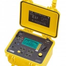
C.A 6547 Megohmmeter
Insulation Resistance Meters
Product Description
5,000 V digital insulation tester with storage & communicationIn its site-proof case, the C.A 6547 megohmmeter can be used for quantitative and qualitative analysis of insulation. It also automatically measures voltage, capacitance and residual current. In addition, this model offers storage of measurements and an RS 232 link for controlling the instrument and processing the data using the Megohmeter software.Functions and specifications:
measurement range: 10 kΩ to 10 TΩ
4 fixed test voltages: 500 / 1,000 / 2,500 and 5,000 V
adjustable test voltage position: 40 to 5,100 V in 10 V or 100 V increments
large backlit LCD screen with digital display and bargraph
quantitative insulation analysis: DAR, PI and DD (dielectric discharge) quality ratios calculated automatically and R(t) curve plotted
large number of functions: programmable test duration, test voltage locking, smooth function, programmable alarms, etc.
storage of several thousand measurements
RS 232 connector for connection to PC (Megohmeter data processing software) or very compact serial printer
power supply: NiMH rechargeable battery for 30 days' operation with 10 DAR measurements and 5 PI measurements per day
electrical safety: IEC 61010-1 Cat.III 1000V or Cat.I 2500V and IEC 61557
dimensions: 270 x 250 x 180 mm; weight: 4.3 kg
Product Brochure :
https://www.chauvin-arnoux.co.uk/sites/default/files/D00VEC36.PDF
Siglent SDS2352X-E
Siglent Oscilloscopes
Product Description
The Siglent SDS2000X-E is a very high quality two channel digital storage oscilloscope. It features a real-time sample rate of up to 2 GSa/s and a bandwidth of up to 350 MHz along with a standard record length of 28 Mpts.
The SDS2000X-E Series Oscilloscopes use a new generation of advanced SPO technology for an excellent signal fidelity and very low background noise. It has a minimum vertical input range starting from 500 µV/div and an innovative trigger system with high sensitivity and low jitter.
This high performance standard not only ensures capturing real-time instantaneous signals, but also observes details of repeated signals.
The SDS1000X-E has a refresh rate of up to 110.000 wfms/s, enabling users to capture instantaneous signals, as well as abnormal signals more quickly.
It also helps to enhance the waveform capturing ability and to expedite a circuit debug course. The large TFT color displays are very easy to read. Thanks to an intelligent system for displaying or masking information, the largest possible area is always available for displaying signals. The signal curves, the FFT display, and other functions can be shown simultaneously on the display.
The oscilloscopes of the Siglent SDS2000X-E series have enhanced mathematical functions. Measurements and math functions are processed over the complete memory range, not only in the display memory.
In addition the FFT function works with a lot more data points (1 MPts instead of 16 KPts) which makes it more accurate.
Model
SDS2202X-E
SDS2352X-E
Bandwidth
200 MHz
350 MHz
Sample Rate (max)
2 GSa/s
2 GSa/s
Waveform Capture Rate
110000 wfms/s
110000 wfms/s
Memory Depth
28 MPts
28 MPts
Display
17,78 cm / 7 inch (800x480)
17,78 cm / 7 inch (800x480)
Channel
2
2
Waveform Generator
Option
Option
Logic Analyzer
Option
Option
Serial Decoder
Yes
Yes
Special Features
Serial Decoder included
With the signal decoder and trigger functions of the Siglent SDS2352X-E serial protocols events can be easily isolated and analysed. The decoded details are shown directly on the waveform with an intuitive, color coded overlay.
Deep Memory (14 Mpts)
The Siglent SDS2352X-E oscilloscope can store up to 14 million measurement points. Simply zoom into a selected part of the captured waveforms to get more details and scroll within the measurement points. The 1 GSa/S, 14 Mpts architecture provides the ability to capture a fast transient or a long acquisition.
Innovative SPO technology
With the "Super-Phosphor" Oscilloscope (SPO) and its multi-level intensity grading display, extensive signal characteristics with a very large number of measurement values can also be displayed completely. A color display option changes the intensity grading into a color temperature display. The more often a waveform appears, the warmer the color is.
Gate and Zoom measurement
Through Gate and Zoom measurement of the Siglent SDS2352X-E, the user can specify an arbitrary interval of waveform data analysis and statistics. This helps avoid measurement errors that can be caused by invalid or extraneous data, greatly enhancing the measurements’ validity and flexibility.
Advanced Math Functions and FFT
The SDS1000X series supports several math operations (addition, subtraction, multiplication, division), FFT (Fast Fourier transform) operation and math function operation (differential, integral, square root). The measurements and math functions of the Siglent SDS2352X-E are greatly enhanced, they use the complete memory instead of the display memory. In addition the FFT function uses up to 1 million points(SDS1104X-U 128kPts).
Masked Pass/Fail-Tests
One way to verify a waveform's compliance to a particular set of parameters is to use pass/fail testing. A pass/fail defines a region of the oscilloscope's display in which the waveform must remain in order to comply with chosen parameters. Compliance to the mask is verified point-by-point across the display. Features: User defined masks, Pass/Fail counts, Stop on Fail, Fail Alarm
Auto measurements with statistics
The Siglent SDS2352X-E measures up to five parameters like rise- and fall-time, amplitude, pulse width, duty cycle and many more simultaneously and shows statistics for every parameter (current, mean, min, max and other values).
Siglent SDS1102CML+
Siglent Oscilloscopes
Product Description
Low cost 2 channel DSO with 100 MHz bandwidth, 1 GSa/s and 2 Mpts memory. High quality, great price-performance ratio.
This Siglent SDS1102CML+ is a high quality two channel digital storage oscilloscope. It offers a real-time sample rate of up to 1 GSa/s, up to 100 MHz of bandwidth and a memory depth of 2 Mpts.
These Siglent SDS1000CML+ oscilloscopes are entry level-devices at affordable pricing without compromising on quality. The low pricing level results from the large amount of units sold as well as substantial economies. They are equipped with well designed and easy to use control panels offering comprehensive ease-of-use functions for all measuring tasks. The menu navigation is very intuitive.
The particularly large TFT color displays are very easy to read. Thanks to an intelligent system for displaying or masking information, the largest possible area is always available for displaying signals. The signal curves, the FFT display, and other functions can be shown simultaneously on the display.
Models
SDS1102CML+
SDS1152CML+
Bandwidth
100 MHz
150 MHz
Sampling Rate (max.)
1 GSa/s
1 GSa/s
Memory Depth
2 Mpts
2 Mpts
Channels
2
2
Special Features
Plus Version
The + version of the Siglent SDS1000CML+ series features some major improvements towards the previous non + version, as there are:
a higher display resolution (800×480 instead of 480×234)
a front panel redesign
a LAN interface
a memory repartition (more waveform recording memory, less memory for internal saved waveforms)
Cursor Measurements
Cursors report absolute and relative values in the Time and Volt axes of the main display. They may be manually or automatically adjusted to measure features of interest or set to track automatic measurements such as peak or RMS voltages, time periods and more.
Automatic Measurements
The Siglent SDS1000 oscilloscopes offer 32 different automatical time and voltage measurements for easy signal analysis.
Alternate Trigger
It is possible to trigger both channes independently to display signals with different frequencies.
Slope Trigger
Triggers on the signals rise or fall time using user defined parameters.
Digital Filter
Unique digital filters like High pass, Low pass, Band pass or Band Stop filters may improve the signal quality.
Pass / Fail Test
The Pass/Fail function monitors the changes of signals by comparing whether the input signal is within the pre-defined mask. The testing results not only can be displayed on screen or output by isolated pass/fail port, but also can be alarmed according to turn on system sound.
Fast Fourier Transformation
The FFT function provides spectrum analysis function for users. Supported FFT windows: Rectangle, Hanning, Hamming, Blackman.
USB Stick Support
The device supports an easy-to-use file system. It allows for both USB flash drive and local file storage.
Waveform Recorder
The Waveform Recorder can record input waveforms from CH1 and CH2 with a maximum record length of 2500 frames. This record behavior can also be activated by the pass/fail test output, which makes this function especially useful to capture abnormal signals in long term without keeping an eye watching it.
Specifications
General Data
Siglent SDS1102CML+
Display
7" (17.78 cm) TFT true color LCD
Resolution
800 × 480 Pixel
Size
323 × 157 × 135 mm
(12.7" × 6.1" × 5.3")
Weight
2500 g (5.51 lbs)
Oscilloscope Details
Siglent SDS1102CML+
Channels
2
Real-time sample rate
1 GSa/s real time
Bandwidth
100 MHz
Sampling mode
Normal, average, peak detect
Mathematics
A+B, A-B, A×B, A/B, FFT (Fast Fourier Transform)
FFT windows
Rectangle, Hanning, Hamming, Blackman
Signal
Siglent SDS1102CML+
Max. Input voltage
400 Vrms CAT I
Real-time sample rate
up to 1 GSa/s real time
Time base
5 ns/Div. to 50 s/Div.
(Steps 1 - 2.5 - 5)
Memory
2 Mpts (1 channel)
1 Mpts (2 channels)
Vertical
Siglent SDS1102CML+
Analog digital converter (A/D)
8 bit
Sensitivity range (V/div)
2 mV/Div to 10 V/Div.
Displacement range
±10 Div. (2 mV - 10 V)
Trigger
Siglent SDS1102CML+
Trigger
Channel 1, Channel 2, Ext, Ext / 5, AC Line
Signal system and line/field frequency (Video triggering mode)
Support the NTSC, PAL and SECAM broadcasting systems of any field or line frequency.
Measurement
Siglent SDS1102CML+
Cursor measurement
Manual, Track and Auto Measure modes
Auto measurement
Vpp, Vmax, Vmin, Vamp, Vtop, Vbase, Vavg, Mean,Crms, Vrms, ROVShoot, FOVShoot, RPREShoot, FPREShoot, Rise time, Fall time, Freq, Period,+ Wid,-Wid, +Dut, -Dut, BWid, Phase, FRR, FRF, FFR, FFF, LRR, LRF, LFR, LFF
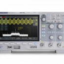
Siglent SDS1104X-U 100MHz Four channel oscilloscope
Siglent Oscilloscopes
Product Description
SIGLENT’s SDS1000X-U Series Super Phosphor Oscilloscopes is available in one bandwidth, 100 MHz. It has a maximum sample rate of 1 GSa/s and a maximum record length of 14 Mpts. For ease of use, the most commonly used functions can be accessed with its user-friendly front panel design.
The SDS1000X-U series employs SPO (Super Phosphor Oscilloscope) technology that provides excellent signal fidelity and performance. It comes with an innovative digital trigger system with high sensitivity and low jitter, and a waveform capture rate of 400,000 frames/sec (sequence mode). The SDS1000X U also employs a 256 level intensity grading display function and a color temperature display mode not found in other models in this class.
Another powerful addition is the new 128 k point FFT math function that gives the SDS1000X-U very high-frequency resolution when observing signal spectra. SDS1000X-U also supports searching and navigating. The features and performance of SIGLE NT’s new SDS1000X-U cannot be matched anywhere else in this price class.
Key Features
100 MHz bandwidth
Real-time sampling rate up to 1 GSa/s
The newest generation of SPO technology
Waveform capture rates up to 100,000 wfm/s (normal mode) and 400,000 wfm/s (sequence mode)
Supports 256-level intensity grading and color temperature display modes
Record length up to 14Mpts
Digital trigger system
Intelligent trigger: Edge, Slope, Pulse Width, Window, Runt, Interval, Time out (Dropout), Pattern
Serial bus triggering and decoding (Standard), supports protocols IIC, SPI, UART, CAN, LIN
Video trigger, supports HDTV
10 types of one-button shortcuts, supports Auto Setup, Default, Cursors, Measure, Roll, History, Display/Persist, Clear Sweep, Zoom and Print
Segmented acquisition (Sequence) mode, divides the maximum record length into multiple segments (up to 80,000), according to trigger conditions set by the user
Automatic measurement function for 38 parameters as well as Measurement Statistics, Zoom, Gating, Math, History and Reference functions
History waveform record (History) function (maximum recorded waveform length is 80,000 frames)
128 k pts FFT, supports Peaks and Markers
Math functions (FFT, addition, subtraction, multiplication, division, integration, differential, squareroot)
Large 7 inch TFT LCD display with 800 * 480 resolution
128k points used to calculate the FFT
The new math co-processor enables FFT analysis of incoming signals using up to 128k samples per waveform. This provides high frequency resolution with a fast refresh rate. The FFT function also supports a variety of window functions so that it can adapt to different spectrum measurement needs. Four-channel series support Peaks, Markers, a variety of numbers.
Waveform Capture Rate Up to 400,000 wfm/s
With a waveform capture rate of up to 400,000 wfm/s (sequence mode), the oscilloscope can easily capture low-probability events.
Accessoires Included:
1 x Siglent SDS1104X-U Oscilloscope4 x 100MHz probes1 x Guarantee Card1 x Power Cord1 x USB Cable1 x Quick Start Guide
Optional Accessories:
Siglent BAG-S1 Soft Carry Case
Siglent's STB-3 Oscilloscope Demo / Training Board
Siglent SDS1000X-E-RMK Rack Mount (SDS1000X-E, SDS2000X-E series)
Siglent ISFE Isolated Front End module
Specifications Download
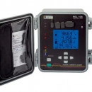
PEL106 POWER ENERGY LOGGER
Loggers
Product Description
Highlights
• IP67 all-terrain casing resistant to shock, UV light and high temperatures• Communication via Wifi, 3G-UMTS/GPRS, LAN (Ethernet), Bluetooth and USB• Self-powered via its voltage inputs up to 1,000 V• Continuous recording with an interval of 200 ms between measurements• Measurements as per the IEEE 1459 standard• 4 voltage inputs & 4 current inputs• Ideal for installation on electricity poles
Description
The PEL106 power logger measures and records all the useful data for energy consumption diagnostics. The PEL106 can be used without cutting off the mains power supply.
ErgonomicsRugged thanks to its IP67 all-terrain casing, the PEL106 can be transported anywhere. It is equipped with 4 voltage channels and 4 current channels. No more battery problems: this logger is self-powered directly via the phase. The LCD screen with backlighting and a quadruple digital display is particularly easy to read. The PEL 106 is equipped with an SD/SD-HC card for backup of the data from several months or even years.
MeasurementsSuitable for all types of electrical networks, the PEL106 automatically recognizes the sensors connected. It measures voltage up 1,000 VAC/VDC and current up to 10 kVAC / 5 kVDC. Its wide measurement ranges enable it to record power values up to 10 GW/Gvar/GVA, and energy up to 4 EWh/EVAh/Evarh. It is equipped with an Alarm mode. The user can define limits and a list of events is recorded.
Analogue measurementsWhen used with remote L452 loggers, the PEL106 can recording external parameters such as the temperature, pressure, engine torque, etc., and thus refine the analysis if you are troubleshooting malfunctions, for example. This function on the PEL106 is ideal for applications involving new energies such as wind (electrical energy linked to the strength of the wind).
Ultra-communicatingThe PEL106 is equipped with multiple communication modes: USB, Ethernet, Bluetooth, Wifi and 3G/GPRS. The new 3G/GPRS mode allows users to insert a SIM card in the PEL for remote connection via a GSM. When an alarm is triggered, users can automatically receive an email alert.When access to the PEL106 is complex due to protective measures on secure IT networks, the measurements can be viewed via an IRD server.
SoftwareThe PEL Transfer software can be used to analyse the data recorded with the PEL100 models. On the basis of the power measurement campaigns performed, the software automatically provides a breakdown of the losses detected.New: the software directly calculates the cost of the power consumed and gives the result in the local currency selected. The DATAVIEW software platform can be used to generate reports. Users can set alarm thresholds on the various measurements made in order to obtain a customized measurement report.
Additional specifications:Acquisition interval from 200msVoltages, currentActive, apparent and reactive power valuesPhase: cos phi, tan PHI, PFTHD Harmonics IP67 closed, IP54 open
Download Brochure / Specifications :
PEL100 Specifications Download
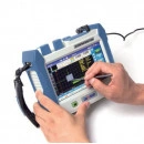
Deviser AE3100A, 30/28 dB Single Mode OTDR, Wavelength 1310/1550 nm
OTDRs
Product Description
Deviser AE3100A Single Mode OTDR Instrument’s 4th generation OTDR, field-portable, a giant leap forward in fiber-optic measurement performance and utility.
Power Meter & VFL includedDynamic Range: 30/28 dBOTDR Type: Dark Fiber TestingDisplay Size: 5 inchDisplay Type: Outdoor-Enhanced, 800×480 TFTOperation Access: Touchscreen
Brand:
Deviser
Dynamic Range:
30/28 dB
OTDR Type:
Dark Fiber Testing
Display Size:
5 inch
Display Type:
Outdoor-Enhanced, 800×480 TFT
Operation Access:
Touchscreen
Internal Data Storage:
10,000 OTDR Traces
Interfaces:
2x USB2.0 Ports, 1x RJ-45 and 1x TF Card Port(64GB max).
Power Supply:
AC/DC Adapter (O/P 12V DC 25W)
Battery Type:
Rechargeable Lithium Polymer
Battery Backup:
8 Hrs
Dimension:
206 x 171 x 75 mm
Weight:
2 Kg
Application type:
Last Mile-Access Links (CATV and Telecom)
Hardware type:
Non-Modular
Wavelength:
1310/1550 nm
Firmware Type:
Linux
Event Dead Zone:
1.5 m
Attenuation Dead Zone:
6 meter
Sampling Points:
Up to 2,56,000 points
Pulse Width:
3 ns to 20 us
HS-12Thermal Stripper for Both Single and Ribbon
Fibre Optic
Product Description
The FiberFox HS-12 newly developed hand-held thermal stripper is rugged and durable, yet small in size and light weight. Designed to strip the jacket of single fiber and ribbon cable up to 12 fibers, it offers extreme convenience under any tough environment. Benefits include fast heating time of 4 seconds and approximately 500 cycles with a fully charged battery. So easy to use that anyone can do clear stripping with near zero failure
For Both Single and Multi-Fiber Cable Stripper
Accurate, Rugged and Easy to use!!
Features
Long-lasting Thermal Stripper for both ribbon fiber and single fiber cable
World’s fastest heating time of 4sec
Long lasting battery: Approximately. 500 times with a full charged battery by simple operation
Size and Weight
Height: 1.33 inches (34 mm)Width: 5.47 inches (139 mm)Depth: 1.33 inches (34 mm)Weight: 0.66 pounds with battery (302grams)0.57 pounds without battery (260grams
** Removable Fiber Holders are needed (Included in a splicer kit or sold Separately)
Specification
Fiber Material
Silica glass
Coating Material
UV cured resin
Coating Thickness
“Single fiber: 0.25~0.4mm 2 to 12 Ribbon fiber: 0.3~0.4mm”
Cladding Diameter
125μm
Coating Removal Length
max 30mm
Heating Mode
Normal mode / Power save mode
Temperature Settings
Normal mode: approx. 80℃, 95℃, 110℃, 130℃Power save mode: approx. 70℃, 80℃, 95℃, 110℃
Fiber Holder Type
FH-2, FH-4, FH-6, FH-8, FH-10, FH-12, FH-250, FH-900,FH-U (Universal Holder both for 250μm and 900μm)
Power Supply Method
AC drive: AC100~240V, 50/60Hz
Operating Condition
Temperature: 0℃~40℃ / Humidity: 0%~95%
Applicable Fiber Type
Single fiber: 250μm, 900μm, 3.0mm fiber cable and flat cableRibbon fiber: 2 to 12 ribbon fiber cable
Heating Time
Approx. 4~5sec at normal modeApprox. 5~6sec at save mode
Battery Capacity
Approx. 500 stripping with 12 ribbon fiber with a full charged battery
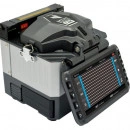
FiberFox Mini12R Ribbon Splicer
Fusion Splicers
Product Description
Mini 12R+
The Smallest and the Lightest Ribbon Fiber Fusion Splicer
Size: 4.8 x 4.88 x 5.4 (in)Weight: 2.77lbs. (w/o battery)
Fastest Splicing Time15 sec with single mode fiber20 sec Heating time* 9 sec with continuous heating mode
Comes with 2 Battery PacksFull Touch ScreenMPO SOC Compatible
Specification
Applicable Fiber
SMF(G.652/657), MM(G.651), DSF(G.653), NZDS(G.655)
Fiber Count
Single to 12 Rebbon Fiber
Cladding dia./Sheath dia.
Single:125 / 160 to 3mm by Fiber Holder SystemRiboon:125 / Ribbon Fiber Thickness 0.25 to 0.4mm
Average Slice Loss
0.03bB(SM), 0.02db(MM), 0.08dB(DS) and 0.08dB(NZDS)Measured by cut – back method relevant ITU-T and IEC standards
Splice Mode/Heating Mode
100 Splice Modes / 32 Heating Modes
Splice Time/Heating Time
15 Sec / 20 Sec
Splice Result Data save
up to 2000 Splices
Viewing Method/Magnification
2 Axis CMOS Camera with 4.3″ Color LCD / 33X and 60X Magnification
Applicable Protaction Sleeve
60mm, 40mm (2.36in, 1.57in)
No. of Splice/Heating per Battery
120 cycles with LBT-50
Electro Life
1500 Splices
LCD Screen
4.3″ Hi-Def Touch Screen w/ Temper proof glass
Optical System
Direct LED (No Mirror)
Weight
2.77 lbs (without battery)
Size
4.8 x 4.88 x 5.4 (in)
Operating Environment
Elevation 0-5,000 meters, 14~140˚F, 0~95% relative humidity
Storage Condition
Temperature -40 to 176˚F, 0~95% relative humidity, battery -4~86˚F
Terminal
USB 2.0 (Mini-B Type) for PC
Pull Test
1.96~2.25N (standard) 4.4N (Optional)
Chauvin Arnoux C.A 6472
Ground Resistance Testers
Product Description
Tester for all types of earth measurements, including pylon earth measurements (with the C.A 6474) - soil resistivity - earth coupling - ground potential - continuity & resistanceThe C.A 6472 can be used for quick, comprehensive surveys of all earthing configurations, offering all the necessary earth measurement functions in a single instrument.When used with the C.A 6474, it can also perform pylon earth measurements, making it a unique but essential tool for diagnostics and maintenance on pylon networks.
The C.A 6472 offers the possibility of analysing the frequency behaviour of the earth connections thanks to its extensive measurement frequency range (41 to 5,078 Hz). The use of a high-frequency measurement signal makes it possible to assess the behaviour of an earthing circuit in the presence of lightning.
Functions:
3P measurement up to 10 kΩ and stray voltages up to 60 V RMS
4P and selective 4P measurement
Earth loop measurement with 2 clamps from 0.01 Ω to 500 Ω
Earth coupling measurement
Soil resistivity measurement: simply program the distances used for the measurement and the tester then calculates r using the Wenner oe Schlumberger methods
Ground potential measurement
Continuity and resistance measurement
Pylon earth measurement with the C.A 6474
Other specifications:
Storage of 512 test results
USB optical link
Ground Tester Transfer PC software to process the stored data
Power supply: NiMh battery with external charger
IP53 protection
IEC 61557 -1 -4 -5
IEC 61010 50V CAT IV
Dimensions: 272 x 250 x 128 mm, 3 kg
Brochure/Specifications Sheet:
https://www.chauvin-arnoux.co.uk/sites/default/files/D00SAJ00.PDF
LC\APC – LC\APC 3m : Single Mode Duplex Patchcord
Fibre Optic
Product Description
LC\APC – LC\APC 3m : Single Mode Duplex Patchcord
Shipping Not Included
ZAR 69.00
LC\APC – LC\UPC 3m : Single mode Duplex Patchcord
Fibre Optic
Product Description
LC\APC – LC\UPC 3m : Single mode Duplex Patchcord
Shipping Not Included
ZAR 69.00
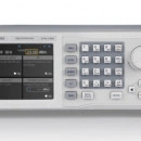
Siglent SSG5040X 9 kHz~4 GHz (CW MODE) Signal Generator
Signal Generators
Product Description
The SIGLENT SSG5040X signal generator can generate analog and vector signals, with a frequency range of 9kHz to 4GHz. The SSG5000X series features the industry-leading performance in phase noise, spectral purity, bandwidth, EVM, output power measurements and tests. The internal IQ modulation generator and waveform playback function make it easy to create even the most complex signal types. They also cover the most important RF band for digital wireless communications and includes standard waveform files.The SIGLENT SSG5040X is a powerful and cost effective source that are ideal for R&D, education and manufacturing.
User interface SSG5000X Series
1. Prompt status bar 2. RF frequency 3. RF level 4. Touch screen display area: Displays the settings under each menu
Use an external USB power sensor to compensate cable losses
Key Features SSG5040X :
Frequency up to 4GHz
0.001 Hz frequency setting resolution
Maximumoutput power up to +26 dBm (typ.)
Phase Noise: -120 dBc/ Hz @ 1 GHz, 20 kHz offset (typ.)
User programmable flatness correction.
Provides AM,FM,PM analog modulation with internal,external or Int+Ext source.
Single pulse, double pulse and pulse traingenerator (option)
Built-in digital communication standard waveform files such as 5G-NR, LTE, WCDMA, WLAN, Blue-Tooth,CDMA
Internal Custom mode generate common IQ signals such as QAM, FSK, ASK, MSK.
Analog differential I/Q outputs
External analog I/Q input
USB-power meter measurement
5 inch TFT capacitieve touch screen,mouse and keyboard supported
Webbrowser remote control on PC and mobile terminals.
Standard interfaces includes USB Host,USB Device (USBTMC), LAN (VXI-11,Socket, Telnet).
Optiona linterface: GPIB
ARB mode to clip the signal of the peak power and display the CCDF (cytotoxic cell diff. factor)
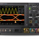
Rigol MSO8204 2 GHz 4-Ch Mixed Signal Oscilloscope
Oscilloscopes
Product Description
The advanced MSO8204 4-channel Digital Oscilloscope brings 2GHz bandwidth, 10GSa/sec maximum sample rate, and 500 Mpts of memory depth. An optional 16-channel logic analyzer interface is also provided to add sophisticated digital debug capabilities.
The 10.1” 1024 x 600 capacitive multi-touch color LCD screen also offers 256-level intensity grading and waveform refresh rate of up to 600,000wfm/sec. The enhanced FFT capability offers real-time spectrum analysis of up to 1Mpts of waveform data. The MSO8000 Series Next Generation User Interface provides users with five distinct ways to interact with the instrument: LCD Touch, traditional button and knob, mouse/monitor, PC control and remote web operation.
The MSO8000 series adopts Rigol’s proprietary “Phoenix” chipset, which allows sampling at 10GSa/s and integrates all of the front-end analog processing. The three models (600MHz, 1GHz, and 2GHz) in the MSO8000 series provide non-stop recording and playback for a maximum of 450,000 frames of hardware real-time waveforms using a segmented storage technique. Trigger conditions can be set to make a selective choice in capturing and saving the signals of interest.
With a total of seven unique integrated instruments (digital oscilloscope, 16-channel logic analyzer, spectrum analyzer, optional 2-channel 25MHz arbitrary waveform generator, digital voltmeter, 6-digit frequency counter and totalizer, and optional protocol analyzer, 43 Precision Measurements, Power, Histogram, FFT and other analysis capabilities, the MSO8000 Series allows customers to quickly identify and resolve complex design and debug challenges. The optional Protocol Analyzer supports RS232/UART, I2C, SPI, CAN, LIN, I2S, FlexRay, and MIL-STD-1553 serial bus. The protocol trigger and decoding operate on both the analog channel and the digital channels: RS232/UART, I2C, and SPI protocols, which also a support the waveform search function. The Jitter firmware option supports real-time eye diagram and jitter analysis. The range is field-upgradeable to higher bandwidths.
The MSO8000 series is equipped with hardware pass/fail test function as the standard configuration, which can be used in signal monitoring for a long time, signal monitoring during design, and signal test in the production line. Set the test mask based on a known "standard" waveform, and then an automatic comparison with the signal under test can show a successful or failed test.
Features
Analog bandwidth: 600 MHz, 1 GHz, and 2 GHz (single-channel and half-channel modes)
4 analog channels, 1 EXT channel, and 16 standard configuration of digital channels (required to purchase the probe)
Up to 10 GSa/s real-time sample rate
Up to 500 Mpts memory depth (standard)
High waveform capture rate (over 600,000 waveforms per second)
Up to 450,000 frames of hardware real-time and ceaseless waveforms recording and playback functions
Integrates 7 independent instruments into 1, including digital oscilloscope, 16-channel logic analyzer, spectrum analyzer, arbitrary waveform generator (option), digital voltmeter, 6-digit frequency counter and totalizer, and protocol analyzer (option)
Auto measurement of 41 waveform parameters; full-memory hardware measurement function
A variety of math operations, built-in enhanced FFT analysis, and peak search function
Waveform histogram analysis (standard)
Independent search, navigation keys, and event table
Real-time eye diagram and jitter analysis software (option)
Built-in advanced power analysis software (option)
User-defined one-key quick operation
10.1-inch capacitive multi-touch screen, 256-level intensity grading display, with color persistence
Multiple interfaces available: USB HOST&DEVICE, LAN(LXI), HDMI, TRIG OUT, and USB-GPIB
Web Control remote command
Unique online version upgrade
Sophisticated and convenient industrial design, easy to operate
Includes
USB cable [CB-USBA-USBB-FF-150]
4 passive high-impedance probes (500 MHz) [RP3500A]
2 passive low-impedance probes (1.5 GHz, only for MSO8204/MSO8104)
Front panel cover [MSO8000-FPC]
Quick guide (hard copy)
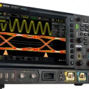
Rigol MSO8064 600MHz 4-Ch Mixed Signal Oscilloscope
Oscilloscopes
Product Description
The advanced MSO8064 600MHz 4-channel Digital Oscilloscope offers 10GSa/sec maximum sample rate, and 500 Mpts of memory depth. The 10.1” 1024 x 600 capacitive multi-touch color LCD screen also offers 256-level intensity grading and waveform refresh rate of up to 600,000wfm/sec. The enhanced FFT capability offers real-time spectrum analysis of up to 1Mpts of waveform data. The MSO8000 Series Next Generation User Interface provides users with five distinct ways to interact with the instrument: LCD Touch, traditional button and knob, mouse/monitor, PC control and remote web operation.
An optional 16-channel logic analyzer interface is provided to add digital debug capabilities. A two-channel 25MHz arbitrary waveform generator is also available.
The MSO8000 series adopts Rigol’s proprietary “Phoenix” chipset, which allows sampling at 10GSa/s and integrates all of the front-end analog processing. The three models (600MHz, 1GHz, and 2GHz) in the MSO8000 series provide non-stop recording and playback for a maximum of 450,000 frames of hardware real-time waveforms using a segmented storage technique. Trigger conditions can be set to make a selective choice in capturing and saving the signals of interest.
With a total of seven unique integrated instruments (digital oscilloscope, 16-channel logic analyzer, spectrum analyzer, optional arbitrary waveform generator, digital voltmeter, 6-digit frequency counter and totalizer, and optional protocol analyzer, 43 Precision Measurements, Power, Histogram, FFT and other analysis capabilities, the MSO8000 Series allows customers to quickly identify and resolve complex design and debug challenges. The optional Protocol Analyzer supports RS232/UART, I2C, SPI, CAN, LIN, I2S, FlexRay, and MIL-STD-1553 serial bus. The protocol trigger and decoding operate on both the analog channel and the digital channels: RS232/UART, I2C, and SPI protocols, which also a support the waveform search function. The Jitter firmware option supports real-time eye diagram and jitter analysis. The range is field-upgradeable to higher bandwidths.
The MSO8000 series is equipped with hardware pass/fail test function as the standard configuration, which can be used in signal monitoring for a long time, signal monitoring during design, and signal test in the production line. Set the test mask based on a known "standard" waveform, and then an automatic comparison with the signal under test can show a successful or failed test.
The MSO8000 series provides a variety of external interfaces, including USB HOST&DEVICE, LAN(LXI), HDMI, TRIG OUT, and USB-GPIB (option). The oscilloscope is in compliance with the standards specified in LXI Device Specification 2011. It can access to the LXI webpage via the LAN interface.
Features
Analog bandwidth: 600 MHz, 1 GHz, and 2 GHz (single-channel and half-channel modes)
4 analog channels, 1 EXT channel, and 16 standard configuration of digital channels (required to purchase the probe)
Up to 10 GSa/s real-time sample rate
Up to 500 Mpts memory depth (standard)
High waveform capture rate (over 600,000 waveforms per second)
Up to 450,000 frames of hardware real-time and ceaseless waveforms recording and playback functions
Integrates 7 independent instruments into 1, including digital oscilloscope, 16-channel logic analyzer, spectrum analyzer, arbitrary waveform generator (option), digital voltmeter, 6-digit frequency counter and totalizer, and protocol analyzer (option)
Auto measurement of 41 waveform parameters; full-memory hardware measurement function
A variety of math operations, built-in enhanced FFT analysis, and peak search function
Waveform histogram analysis (standard)
Independent search, navigation keys, and event table
Real-time eye diagram and jitter analysis software (option)
Built-in advanced power analysis software (option)
User-defined one-key quick operation
10.1-inch capacitive multi-touch screen, 256-level intensity grading display, with color persistence
Multiple interfaces available: USB HOST&DEVICE, LAN(LXI), HDMI, TRIG OUT, and USB-GPIB
Web Control remote command
Unique online version upgrade
Sophisticated and convenient industrial design, easy to operate
Includes
USB cable [CB-USBA-USBB-FF-150]
4 passive high-impedance probes (500 MHz) [RP3500A]
Front panel cover [MSO8000-FPC]
Quick guide (hard copy)

HTZ Warfare
RADIO NETWORK PLANNING - ATDI
WHAT IS HTZ warfare?
HTZ warfare is a RADIO NETWORK PLANNING and SPECTRUM ENGINEERING SOFTWARE solution for deployment, network optimization and real-time analysis of tactical military communications.
HTZ warfare is a COMPREHENSIVE TOOL for modeling all radio communication technologies in the MF/HF/VHF/UHF/SHF/EHF frequency bands. The software includes Electronic Warfare and tactical communications functions that allow an accurate simulation of the battlefield for advanced tactical mission planning and the analysis of electromagnetic field (ELINT, COMINT).
HTZ warfare offers DIRECTION FINDING, JAMMING, RADAR FEATURES, comprehensive set of radio planning capabilities that enables the design and optimization of military communication networks for frequencies ranging from 8 kHz to 1 THz.
HTZ warfare is aimed at staff at all command levels participating in ELECTROMAGNETIC SPECTRUM OPERATIONS.
HTZ warfare is a flagship military and security radio communications planning system, capable of modeling all radio communications technologies operating between about 8 kHz and 1 THz.HTZ warfare offers the ability to model fixed and mobile radios and to model dynamic scenarios. HTZ Warfare also features powerful database capabilities, and it is possible to connect directly to the SQL database or XML file.HTZ warfare supports different operator modes, provinding a simple interface for beginners and low-level operators, and more advanced options for more experienced operators.HTZ warfare includes sophisticated methods of interference and jamming analysis, including the ability to assess the impact of any technology on any other technology.HTZ warfare provides mission planning support for a wide range of activities such as setting up and managing tactical and infra radio communications networks, including Dynamic Spectrum Allocation (static / temporary / combined).
HTZ warfare FEATURES
COMMUNICATIONS ELECTRONIC WARFARE
SIMULATING RADIO NETWORKS IN THE WARFARE SAVES LIVES
HTZ warfare is the world’s most advanced battlespace RF planning and modelling software for powerful spectrum engineering in tactical mission planning and analysis.
Design and optimization of military communication networks for frequencies ranging from 10 kHz up to 450 GHz
HF, VHF/UHF, PMR, TRS, MW, Satellite, 2G to 5G, WiFi, IoT network modelling and analysis
Accurate simulation of advanced EW mission planning: jammers, radars, DF, interception, UAV/UAS
Optimize site locations, number, power, frequency and efficiency of any radio systems in defense and security networks
Advanced modelling of modern electronic warfare (ELINT, COMINT) battlefield in 2D/3D view
Coexistence scenarios of multiple radio systems across civilian and military networks
Out-of-band interference, inter-modulation calculations and EMC analysis
Air-to-Air, Air-to-Ground, Ground-to-Air communications modelling and analysis
Battleship interference analysis among various near-field radio systems
UAV/UAS MISSION PLANNING
HTZ warfare is the perfect choice for UAV/UAS comes network, which often required to integrate ground-to-air, air-to-air services and complex scenarios of compatibility with other civilian/military communication services.
Aeronautical propagation model ITU-R P. 528
Frequency planning and interference analysis along the way points
Self-healing network planning using mesh technique
Path specific way points coverage and optimization on fly path to overcome connectivity issues
Radar detection avoidance planning by optimization of flying path and altitude optimization
Calculate interference level due to terrestrial networks directly impacting such drones along flight-path
Instantaneous roll, pitch and course modelling; antenna orientation calculation, antenna discrimination along the flying path
MARITIME COMMUNICATION
HTZ warfare supports any communications between sea to sea, sea to air and land to sea communication in maritime communications.The complex scenarios of coverage, interference and intermodulation impact within battleships/ships environment can be examined and simulated to ensure the radio systems in the same vessel are performing effectively and efficiently.
Near-field scenarios in Battleship: HF/VHF/UHF, radar, satellite systems intermodulation analysis
Location optimization of new radio systems against existing radios on board
3D modelling of Battleships/Ships from AutoCAD, ESRI Shape and PDF drawing
Interference analysis against terrestrial radios against satellite earth stations to identify exclusion zones
LMR/PMR/P25/TETRA
HTZ warfare is a proven radio planning solution with its high accuracy in propagation prediction.
Prospective planning to identify the best locations for new sites for greenfield and densification scenarios
Migration analysis from analogue to digital communications
Analysis of outdoor to indoor coverage by signal penetration loss calculation
Population analysis according to points, areas by vector polygon importation or raster files
In-depth coverage study of network coverage, composite coverage, overlapping, best server and network densification
Propagation model tuning by correlation analysis between prediction and measurement
Automated frequency assignment and optimization
Traffic analysis by the ground occupancy, target areas or mesh blocks to cover
Point to Point network analysis: Path profile, Reliability, Automatic optimization of the heights, of the power, frequency and space diversity, frequency analysis
P25 Simulcast planning and analysis
PUBLIC SAFETY NETWORK /PPDR
HTZ warfare supports designing and modelling of TETRA, PMR/DMR, P25 and PS- LTE with the ability to manage coverage, capacity, site parameters and neighbour planning and optimization.
It ensures the highest level of reliability, availability and resilience of critical comms and assist operators to achieve smooth migration to broadband connectivity and new technologies.
Coverage planning
Interference calculations
Capacity planning
Automated handover, neighbour list planning and analysis
Monte Carlo simulations
Automatic site planning
Automatic site optimization
Automatic frequency planning
Traffic & mobility profile editor (end devices)
HF COVERAGE ANALYSIS
HTZ warfare is designed to predict HF Ground-wave and Sky-wave propagation parameters such as Signal to Noise Ratio (SNR), Maximum usable frequency (MUF), Frequency of Optimum Transmission (FOT), Field Strength, Reliability.
Ground-wave propagation based on ITU-R P. 368-9 using conductivity and permittivity properties of the earth to calculate path loss,
Sky-wave for LF/MF at night time using ITU-R P. 1147-2,
Downlink and uplink calculations to offer full reciprocity to users modelling mobile systems,
Study HF signal level at different time of the day at different season,
Sunspot modelling and impact on HF communication,
Calculation of minimum/maximum and optimum frequency for HF communication,
Ship transmitter modelling,
Produce H & V cuts for HF antenna using type, ground conductivity, dielectric constant and operating frequency.
ITU R-533
MICROWAVE Links
HTZ warfare enables microwave link design for networks in any frequency band; an integral propagation model library covers the frequency range 30MHz up to 300GHz.This multi-functional tool enables users to manage multiple technologies in one project.
Profile budget calculations,
Frequency and space diversity,
Multi-K factor calculations,
Climate and rain parameters,
Reliability calculations,
Automatic antenna orientation,
Link optimization,
Automated frequency planning,
Interference calculations,
Quality objectives calculations – ITU-R F. 1703 and ITU-T G.827.
HTZ warfare is intended exclusively for the armed forces, Government security services and Telecom Defense programs. ATDI strictly follows export restrictions defined by the UN, EU, France, United Kingdom, Germany, Poland, Spain, Australia and USA.
NATO code: FA8T9
HTZ warfare current version: V22.6.8 (07-2020)(c) 1988-2020
Brochure
Siglent CP4070 150 KHz 200 Amp Current Probe
Current Probes
Product Description
Siglent CP4070 150 KHz 200 Amp Current Probe
Parameters :
CP4070
Bandwidth:
150 KHz
Maximum Continuous Current:
70 Arms
Peak Current:
200 A
Switching Ratio:
500 mV/A; 50 mV/A
DC Measurement Accuracy:
500 mV/A (20 mA-14 ApK) ±3% ±20 mA; 50 mV/A (200 mA-100 ApK )±4%± 200 mA; 50 mV/A (100 A-140 ApK) ±15%
Power:
9 V battery
Weight
400 gramm
Dimensions
32 x 26 x 9cm ( packing )
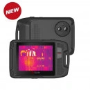
GUIDE P Series Pocket-Sized Thermal Camera
Temperature
Product Description
Application field: Thermography / Power system/ Solar energy / Industrial process / Building inspection
GUIDE P Series Pocket-sized Thermal Camera designed for electrical equipment maintenance and building inspection, which can fast detect the potential problems, report repair data and share images by Wi-Fi. It is a truly handy thermal camera that fits in your pockets for fast and accurate thermal inspections anytime. P Series featured with 3.5-inch LCD touchscreen for simple operation, and support picture-in-picture, smooth zoom, max and min temperature alarm, Cloud Service and more.
Features
Reasonable Layout and Good Ergonomic Design
No interfere between lens area and grip area
Model
P120V
IR image & Optical
IR Resolution
120×90 @17μm
Detector type
VOx/7.5~14μm
Frame Rate
15HZ/9HZ
Thermal Sensitivity / NETD
60 mk
Focal Length
2.28mm/F1.13
Field of view(FOV)
50°×38°
Spatial Resolution(IFOV)
7.6mrad
Focus
Focus-free
Visible Camera
Visible Camera Resolution
320×240, Focus-free
Flashlight
Yes(on/off/flash)
Image Display
Display
3.5" LCD touchscreen display
Display Resolution
320×240
Image modes
IR, Visible, Picture-in-Picture, MIF
Color Palettes
6:Hot Iron, Black Heat, Heat Iron, White Heat, Medical, Arctic
Digital zoom
Smooth zoon, up to 8X
Auto,Semi-automatic, Manual
Temperature Measurement
Measurement Range
-20℃-150℃,100℃-400℃(Auto switching)
Accuracy
±2℃ or ±2%, whichever is greater ( target temp ≥0℃, ambient temp is 15℃ ~ 30℃ )
Measurement Spot
Center spot,and can add one removable measurement spot
Measurement Area
Can add one removable area measurment box
Auto Max & Min Temp Tracking
Full screen auto max & min temp. tracking
Analysis target (area) max & min temp. tracking
Full Screen Max & Min Temp. Alarm
Yes
Image Storage
Storage Media
4G Internal memory,at least 500 sets of images
IR Image Format
Full Radiometric (JPG)
Visible Image
Yes
Connections & Communications
USB
Type-C, for image data transmission with PC
WIFI
Yes, Wi-Fi enabled for data transmission
Mobile APP
Yes,and support Cloud Service
PC IR Analysis Software
Yes
Power system
Battery Tpye
Built-in rechargeable li-thium battery, non- removable
Battery Operating Time
≥2 hours(when wifi-off)
Charging Time
≤1.5 hours
Environmental parameters
Operating Temperature
-10℃~50℃
Storage Temperature
-40℃~70℃
Encapsulation
IP54, 1-meter drop test
Certification
CE, FCC, ROHS
Weight
240g
Size
133mm*87mm*24mm
Standard Accessories
Charger + Adapter, TYPE-C USB cable, Wrist Strap, Pouch, Quick start Guide, Data Download Card
*Technical parameters are subject to change without notice.

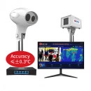
GUIDE IR236 IR Fever Warning System
Temperature
Product Description
Application field: ThermographyInspection and quarantineMedical Diagnosis
GUIDE IR236 IR Fever Warning Systems are applied to mass fever screening in crowded public places, which help to detect people with a potential fever and may contain or limit the spread of the virus through identification of infected individuals showing fever symptoms. GUIDE IR236 combines advanced technology such as thermography human body temperature measurement algorithm and AI intelligent face tracking to make the equipment accurate and easy to use. The IR236 equipped with various powerful functions. Multi-target tracking can ensure that no targets are missed. Custom warning zones and high-temperature shielding settings can avoid interference from other high-temperature objects. When detect the febrile people, it supports automatic warning, tracking and photo taking for storage which is convenient to query and classify management. GUIDE IR236 is the ideal equipment for epidemic prevention in public places such as airports, stations, factories, schools, and commercial centers.
Higher efficiency on temperature detection, for mass fever screening
Temperature screening for multiple people at the same time, no need to stop
Real-time temperature monitoring at any point in the field of view
Safer, temperature screening from several meters away
Take the temperature of passengers while they are standing or moving several meters away, avoiding the close contact required by temperature guns and reducing the risk of infection
(the picture on the left shows the comparison of the IR thermometer gun and GUIDE infrared fever screening system)
Smarter, automatic tracking, warning, photo capturing for storage
Powered by the AI-enabled face tracking technology, the system can automatically focus on people's face and sound an alarm when a person with a fever is identified, giving the inspectors an effective and efficient tool to deal with densely populated and fast-moving scenarios.
AI algorithm, accurate tempearture detection
In the past 20 years, through constant algorithm optimization coupled with software and hardware upgrades, especially in the field of deep learning based on the neural network, which ensure the fast and accurate temperature detection.
Parameters
IR236
Category
Item
Specification
IR detector
IR resolution
400×300
Pixel size
17μm
NETD
≤40mK
Focal Length
9.7mm
FOV
38°*28°
Frame Rate
25Hz
Visible Camera
Resolution
2 million pixels
Frame Rate
25Hz
Temperature Measurement
Range
-10℃~50℃
Accuracy
≤ ± 0.3 ℃ (ambient temperature 16 ~ 32 ℃)
Calibration
Built-in shutter and external black body, automatic calibration after selecting mode
Software functions
Parameter settings
Warning switch and warning threshold value, number of warning targets, warning photos automatic clearing, shielding fixed high temperature objects
Face tracking
Intelligent face tracking, Supported from V1.0.9.0
Real-time preview
Real-time preview of visible and thermal image
Real-time spot temperature detection
Real-time temperature monitoring at any point in the field of view
Automatic tracking
Support automatic tracking for elevated temperatures
Automatic warning
Automatic tracking, warning and photo capturing for storage when people with fevers are identified; Warning while the Black Body is blocked.
Historical records
Support query, classification and deletion of historical warning screenshots
Video recording
Support. The software needs to be upgraded to V1.1.0.9, and equipped with NVR (NVR standard 4T hard disk), support GB28181 protocol to access third-party platforms
Network communication protocol
HTTP、RTSP
Environmental adaptability
Work Temperature
-10 ~ 50 ℃ (ambient temperature 16 ~ 32 ℃)
Storage Temperature
-20 ℃ ~ 60 ℃
Work Humidity
<90% (non-condensing)
Shock
30g 11ms, IEC60068-2-27
Vibration
10HZ ~ 150Hz ~ 10Hz 0.15mm, IEC60068-2-6
Black body
Blackbody target surface uniformity
≤0.1 ℃
Temperature stability accuracy
≤ ± 0.2 ℃ (single point)
Camera head interface
Network interface
Two-way, visible light 100M, infrared 1000M
Camera head power
Input voltage
DC 12V
input power
≤12W
Packaging specifications
Camera head size
173mm×184mm×212mm
Total height (incl. stand)
2200mm
Camera head package
510mm× 440mm × 270mm (subject to actual delivery)
Total weight
≤45kg (subject to actual delivery)
Siglent SDS2102X Plus 2Ch 100MHz 2GSa/s Oscilloscope
Siglent Oscilloscopes
Product Description
Siglent SDS2102X Plus 2 Channel 100MHz 2 GSa/s osciloscope is the 3rd Generation of their 2000 series of oscilloscopes. Five years after Siglent introducuced the very successful SDS2000X. Siglent has continued to implement customer feedback and now presents SDS2000X Plus series. Designed to impress, the X Plus has a feature-rich standard configuration and options that make it a powerful and flexible tool for all general purpose tasks in the lab.
Bode Plot
The SDS2000X Plus can control the built-in waveform generator or any stand-alone SIGLENT SDG device to scan the amplitude and phase response over frequency of passive or active circuits. The data is presented as Bode Plot. This makes it possible to replace expensive network analyzers in less demanding applications.
Excellent Operability
10.1" display with 1024x600 resolution.
Capacitieve touch screen, supports multi-touch gestures, traces can be moved or scaled efficiently by a finger touch.
Built-in web server supports remote control over the LAN port using a web browser.
External mouse and keyboard support
Power Analysis
The Power Analysis option provides a full suite of power measurements and analysis, thus improving the efficiency ofmeasurement in switching power supplies and power devicedesigns.
Key Features
350 MHz, 200 MHz, 100 MHz models with real-time sample rate up to 2 GSa/s. A 500 MHz bandwidth upgrade option is available for 350 MHz models.
SPO technology
Waveform capture rates up to 120,000 wfm/s (normal mode) and 500,000 wfm/s (sequence mode)
Supports 256-level intensity grading and color temperature display modes
Record length up to 200 Mpts/ch, 400 Mpts in total for all 4 channels
Digital trigger system
Intelligent trigger: Edge, Slope, Pulse, Window, Runt, Interval, Dropout, Pattern and Video (HDTV supported). Trigger zone helps to simplify advanced triggering
Serial bus triggering and decoder, supports I2C, SPI, UART, CAN, LIN (Standard) and CAN FD, FlexRay, I2S, and MIL-STD-1553B (optional) protocols
Low background noise, features 0.5 mV/div to 10 V/div voltage scales
10-bit mode provides higher resolution and lower noise
Segmented acquisition (Sequence) mode, dividing the maximum record length into multiple segments (up to 90,000), according to trigger conditions set by the user, with a very small dead time between segments to capture the qualifying event
History waveform record (History) function for up to 90,000 triggered waveforms (frames)
Automatic measurement function on 50+ parameters, supports statistics with histogram and trend
Two Math traces, support 2 Mpts FFT, +, -, x, ÷, d/dt, ∫dt, √, average, ERES, and formula editor
Abundant data processing and analysis functions such as Search, Navigate, Mask Test, Bode plot, Power Analysis (optional) and Counter
16 digital channels (optional)
Built-in 50 MHz waveform generator (optional)
Large 10.1” TFT-LCD display with 1024×600 resolution; Capacitive touch screen supports multi-touch gestures
Multiple interfaces: USB Host, USB Device (USBTMC), LAN(VXI-11/Telnet/Socket), Pass/Fail, Trigger Out
Built-in web server supports remote control by the LAN port using a web browser; Supports SCPI remote control commands
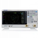
Siglent SVA1075X 9kHz - 7.5GHz Spectrum and Vector Analyzer
Vector Network Analyzers
Product Description
Siglent SVA1075X 7.5GHz spectrum & vector network analyzer is the newest analyzer that represent the highest bandwidth and can be also be extended with Vector Signal Analysis and other options to increase versatility for meeting the unique challenges of RF circuit design.
The SIGLENT SVA1075X spectrum & vector network analyzer is a powerful and flexible tool for RF signal and network analysis. With a frequency range to 7 5 GHz, the analyzer delivers reliable automatic measurements and multiple modes of operation: the base model are a spectrum analyzer and a vector network analyzer, optional functions include a distance to fault locator, a vector signal modulation analyze r. Applications include broadcast monitoring/evaluation, site surveying, S parameter measurement, cable and antenna testing, analog/digital modulation analysis, EMI pre compliance test, research and development, education, production, and maintenance.
Features and Benefits
Spectrum Analyzer Frequency Range from 9 kHz up to 7.5 GHz
Vector Network Analyzer Freq.Range from 100 kHz up to 7.5 GHz
-165 dBm/Hz Displayed Average Noise Level (Typ.)
-98 dBc/Hz.@10 kHz Offset Phase Noise (1 GHz, Typ.)
Level Measurement Uncertainty < 0.7 dB (Typ.)
1 Hz Minimum Resolution Bandwidth (RBW)
Preamplifier Standard
Tracking Generator Standard
Distance To Fault (Opt.)
Analog and Digital Signal Modulation Analysis Mode (Opt.)
EMI Filter and Quasi-Peak Detector Kit(Opt.)
Advanced Measurement Kit (Opt.)
10.1 lnch Multi-Touch Screen , Mouse and Keyboard supported
Web Browser Remote Control on PC and Mobile Terminals and File Operation
Vector Network Analyzer Mode
100k-7.5GHz Vector S11 and S21 measurement, Multi Formats Overlay Display
Modulation Analysis Mode
AM/FM, ASK/FSK/PSK/MSK/QAM Vector Signal Modulation Analysis, EVM evaluation
Model
SVA1015X
SVA1032X
SVA1075X
Spectrum Analyzer Frequency Range
9 kHz~1.5 GHz
9 kHz~3.2 GHz
9 kHz~7.5 GHz
Vector Network Analyzer Frequency Range
10 MHz~1.5 GHz
100 kHz~3.2 GHz
100 kHz~7.5 GHz
Resolution Bandwidth
1 Hz~1 MHz
1 Hz~1 MHz
1 Hz~3 MHz
Displayed Average Noise Level
-156 dBm/Hz
-161 dBm/Hz
-165 dBm/Hz
SSB Phase Noise
<-99 dBc/Hz
<-98 dBc/Hz
<-98 dBc/Hz
Total Amplitude Accuracy
< 1.2 dB
< 0.7 dB
< 0.7 dB
Tracking Generator
5 MHz~1.5 GHz
100 kHz~3.2 GHz
100 kHz~7.5 GHz
VNA measurement
Vector S11,Vector S21
Vector S11,Vector S21
Vector S11,Vector S21
Distance to Fault
VNA Timing Domain Analysis Locator
VNA Timing Domain Analysis Locator
VNA Timing Domain Analysis Locator
Touch Screen
Multi Touch, Mouse and Keyboard supported
Multi Touch, Mouse and Keyboard supported
Multi Touch, Mouse and Keyboard supported
Advanced Measurement
CHP, ACPR, OBW, CNR, Harmonic, TOI, Monitor
CHP, ACPR, OBW, CNR, Harmonic, TOI, Monitor
CHP, ACPR, OBW, CNR, Harmonic, TOI, Monitor
Reflection Measurement
VSWR measurement using Reflection Bridge
VSWR measurement using Reflection Bridge
VSWR measurement using Reflection Bridge
EMI Test
EMI Filter and Quasi-Peak Detector, Log Scale and Limit Line
EMI Filter and Quasi-Peak Detector, Log Scale and Limit Line
EMI Filter and Quasi-Peak Detector, Log Scale and Limit Line
Modulation Analysis
AM, FM; ASK, FSK, MSK, PSK, QAM
AM, FM; ASK, FSK, MSK, PSK, QAM
AM, FM; ASK, FSK, MSK, PSK, QAM
Communication Interface
LAN, USB Device, USB Host (USB-GPIB)
LAN, USB Device, USB Host (USB-GPIB)
LAN, USB Device, USB Host (USB-GPIB)
Remote Control Capability
SCPI/Labview/IVI based on USB-TMC/VXI-11/Socket/Telnet
SCPI/Labview/IVI based on USB-TMC/VXI-11/Socket/Telnet
SCPI/Labview/IVI based on USB-TMC/VXI-11/Socket/Telnet
Remote Controller
SCPI/Labview/IVI based on USB-TMC/VXI-11/Socket/Telnet
SCPI/Labview/IVI based on USB-TMC/VXI-11/Socket/Telnet
SCPI/Labview/IVI based on USB-TMC/VXI-11/Socket/Telnet
Accessoires Included:
1 x Siglent SVA1075X 100kHz - 7.5 GHz With TG and VNA 1 x Guarantee Card1 x Power Cord1 x USB Cable1 x Quick Start Guide
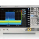
Siglent SSA3050X-R 5GHz Real Time spectrum analyzer
Spectrum Analyzer
Product Description
The SIGLENT SSA3050X-R Real Time spectrum & vector network analyzer has a a capability of 40 MHz analysis bandwidth and 7.2 μs 100% POI, the analyzer can provide multi-dimensions data displays, advanced triggering, and RF data capturing, to solve modern RF spectrum challenges, like hopping frequency, conflict channel, spectrum interference, etc. The Siglent SSA3050X-R also provides standard tracking generator for network analysis, optional wide band digital modulation analysis, and EMI measurement. Applications include broadcast monitoring/evaluation, cellular site, IoT, WiFi, Bluetooth surveying, research and development, education, production, and maintenance.
SSA3050X-R Features and Benefits
Spectrum Analyzer Frequency Range from 9 kHz up to 5.0 GHz
-165 dBm/Hz Displayed Average Noise Level (Typ.)
-98 dBc/Hz.@10 kHz Offset Phase Noise (1 GHz, Typ.)
Level Measurement Uncertainty < 0.7 dB (Typ.)
1 Hz Minimum Resolution Bandwidth (RBW)
Preamplifier Standard
Tracking Generator Standard
Up to 40 MHz Real Time Analysis Bandwidth (Opt.)
100% POI 7.20 μs, Dynamic Range 60 dB
Multi-view for Density, Spectrogram, PvT and 3D
Advanced Measurement Kit (Opt.)
Reflection Measurement Kit (Opt.)
Modulation Analysis Mode (Opt.)
EMI Measurement Mode (Opt.)
10.1 inch Multi-Touch Screen , Mouse and Keyboard supported
Web Browser Remote Control on PC and Mobile Terminals and
File Operation
Real Time Analysis Mode
Density,3D,Spectrogram,PvT,Multi-view and dimensions to monitor complex signals
Modulation Analysis Mode
AM/FM, ASK/FSK/PSK/MSK/QAM Vector Signal Modulation Analysis and EVM evaluation, and Data recording to PC. The analysis BW is same with real-time BW in RTSA mode
EMI Measurement Mode
EMI Measurement with CISPR 16-1-1 EMI filter ,Quasi-peak Detector, and pre-stored standards.
Model
SSA3050X-R
Frequency Range
9 kHz~5.0 GHz
Resolution Bandwidth
1 Hz~3 MHz
Displayed Average Noise Level
-165 dBm/Hz
SSB Phase Noise
<-98 dBc/Hz
Third-order intercept(TOI)
+14 dbm
Total Amplitude Accuracy
< 0.7 dB
Tracking Generator
100 kHz - 5.0 GHz
Real Time Band Width
25 MHz, 40 MHz (Option)
SFDR
60 dB
100% POI
7.20 μs
7.20 μs
7.20 μs
RTSA Measurement
Density, Spectrogram, 3D, PvT
Touch Screen
Multi Touch, Mouse and Keyboard supported
Advanced Measurement
CHP, ACPR, OBW, CNR, Harmonic, TOI, Monitor
Modulation Analysis
AM, FM, ASK, FSK, MSK, PSK, QAM
Reflection Measurement
VSWR measurement using Reflection Bridge
EMI Measurement
EMI Filter and Quasi-Peak Detector, Log Scale and Limit Line
Communication Interface
LAN, USB Device, USB Host (USB-GPIB)
Remote Control Capability
SCPI/Labview/IVI based on USB-TMC/VXI-11/Socket/Telnet
Remote Controller
NI-MAX, Web Browser, Easy Spectrum software, File Explorer
Accessoires Included:
1 x Siglent SSA3050X-R 9kHz - 5.0 GHz 1 x Guarantee Card1 x Power Cord1 x USB Cable1 x Quick Start Guide
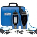
LanTEK IV 500MHz/3000MHz- Cat 6A-Certifies up to Cat 8 standards
Cable Testers
Product Description
The future of copper and fibre cable certification
7 second test time for Cat 6A
Unique VisiLINQ™ permanent link adapters
Certifies up to Cat 8 standards
Measures TCL and Resistance Unbalance
Pre-configuration eliminates setup errors
Sapphire Care Plan minimises costs
Overview
The LanTEK IV cable certifier brings a new standard to the industry, saving you time and improving profitability. It’s time to change the way you certify.
Futureproof and Fast Certifier
A copper and fibre cable certifier, it can test and save a Cat6A link in 7 seconds and certifies links up to Cat8.1 and Cat8.2, including TCL and Resistance Unbalance measurements. Plus, LanTEK IV future-proofs your investment – it will sweep to 3000MHz providing room for future ISO/TIA test standards.
VisiLINQ permanent link adapters
With unique VisiLINQ™ permanent link adapters, there is no need to even hold the certifier. Everything you need is in the palm of your hand – this is a totally new way to certify that will boost productivity.
Complete Connectivity
An intuitive user interface and high-resolution touch screen make LanTEK IV simple to use with no compromise on functionality. For example, LanTEK IV can connect you to the internet and to the new IDEAL AnyWARE Cloud management system, allowing real time collaboration between Project Managers and Field Technicians.
Work smarter not harder with the unique VisiLINQ™ Permanent Link Adapter
VisiLINQ™ enables Field Technicians to initiate testing and view the results all without the need to carry or touch the certifier.
Field replaceable Permanent Link Adapter Tips
The RJ45 tip on the VisiLINQ™ Permanent Link Modules are field replaceable to reduce the cost of ownership, independently verified for 2,000 insertions which is 1,250 more than regular patch cord plugs rated to ISO/TIA standards.
Team Viewer Live Support
Project Managers can connect to a LanTEK IV on the jobsite using the IDEAL AnyWARE Cloud to troubleshoot failed links therefore minimizing troubleshooting time, increasing collaboration and reducing call-backs.
Access can be granted to cable manufacturers and IDEAL Networks Technical Support to allow further troubleshooting if required.
The new IDEAL AnyWARE Cloud management system allows real time collaboration between Project Managers and Field Technicians. There is no need for Field Technicians to setup the LanTEK IV, Project Managers pre-configure the jobs and tests in the IDEAL AnyWARE Cloud, eliminating potential mistakes and compressing the time taken to prepare reports for customers and warranties.
Cloud software
Operates anywhere with a web browser – IDEAL AnyWARE Cloud operates on a PC, Mac and tablet devices (Android and iOS)
Free storage – No need for separate servers or backup systems.
Easy to find project files – Attach all project files including cable layout drawings, videos, and photos into the IDEAL AnyWARE Cloud. Everything you need in one place.
Share reports easier – Use IDEAL AnyWARE Cloud to share links to the test reports eliminating the need to manually email large attachments.
Reduce training time with WalkMe – IDEAL AnyWARE Cloud is embedded with the WalkMe digital adoption platform providing proactive, step-by-step guidance on all key tasks.
Fleet Management
Easily manage the certifier fleet – Fleet manager allows you to see who has the certifier, when the software was last updated, calibration due date and when the results were last synced. Allowing you to manage tester downtime and ensuring results are transferred back to the office and not lost or deleted.
Pre-configuration
Reduce setup errors – Project Managers pre-configure all project information in the IDEAL AnyWARE Cloud and Field Technicians simply download the project to the LanTEK IV eliminating any mistakes from manual data entry.
Create the most complex test ids – Easily create simple or sophisticated naming conventions required by the client.
Troubleshooting
Advanced filtering – filter tests on any field to reduce the time spent searching.
Support
Reduce training time – The IDEAL AnyWARE Cloud comes with proactive, step-by-step guidance for all the key features.
Team Viewer Live Support – Using the IDEAL AnyWARE Cloud users can connect to a LanTEK IV remotely to troubleshoot failed links, minimising troubleshooting time, increasing collaboration and reducing call-backs.
Professional reports
Customer profiles – Create a profile for each of the customers with their company logo, address and contact details. This information is automatically pulled through to the reports, saving time.
2 Report Formats
Single line report – This is a summary report showing multiple tests per page.
Brief report – This is a comprehensive report with all the measurement results with one page per test.
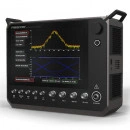
Astronics Freedom R9000
Communication Monitors
Product Description
The R9000 is the first and only LTE-ready test set that also supports the full range of digital and analog LMR protocols. But that’s only the beginning of its capabilities.
Look at this partial list of the R9000’s features and capabilities:
6GHz Frequency Range
Fully portable (less than 17 pounds) targeting better than 4 hour battery life
Full-color multi-touch display
LTE capable (25MHz instantaneous bandwidth; 160MHz in future releases)
Vector Network Analyzer (VNA)
Industry-best spectral purity (-110 dBc/Hz @20khz offset)
Configurable connector access (front and top access models available)
P25 Phases 1 and 2
DMR, NXDN, TETRA
AutoTune™ automated test and alignment options
Standard Features:
Frequency Range from 10MHz to 6GHz.
Analog modulation and demodulation (AM, FM and Single SideBand).
50 W continuous input power and up to 150W peak input power.
Output level to -130 dBm
Spectrum Analyzer
Signal Generator
Oscilloscope
Vector Network Analyzer
Integrated Audio Generators
Audio Quality Tests (SINAD, THD)
Additional Options (available in 2020):
All major digital LMR protocols: P25 Phases 1 &2, TETRA, DMR, NXDN and dPMR
Interference Analyzer
AutoTunes: Test and Alignment
I/Q Recorder and Playback
LTE test options
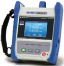
Deviser OM6200 Optical Power Meter
Power Meters and Light Sources
Product Description
The OM6200 is a portable, new generation optical power meter offers a wide measurement range, high accuracy and resolution, insertion loss testing, and good cost-performance. The OM6200 is customized to support optical power measurement of multiple wavelengths between 850nm and 1650nm.
Please click here for more information: Deviser OM6200 Optical Power Meter
View results 1 to 96 from 180