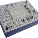
Power Electronics Lab
Bread Board Trainers
Bread Board Trainers
Product Description:
Power Electronics Lab is used to perform power electronics circuit experiments. It is very useful in power electronics laboratories for performing power experiments in colleges and universities. It is very for student to know about the characteristics of power electronics devices and theapplications of power devices. The applications or power devices are in alarm circuit, lamp flasher, rectifiers, choppers, invertors. It is also usedfor commutation circuits.The Equipment is Useful for Students at level in engineering / technical institutes (EC & Telecom) Technical training centers in communicationorganizations, R&D personal and practicing engineering in research labs and industry.
Technical Specifications: DC Power Supply on Board
• ± 5V at 100mA
• ± 12V at 150mA
• ± 15V at 50mA
• ± 35V at 50mA
AC Power Supply on Board : 18V - 0V - 18V at 50mA
• 15V - 0V - 15V at 50mA
Triggering Circuit on Board
Frequency range
Amplitude
: 5 gate signal output
: 40Hz to 900Hz Variable
: 12V
PWM control of G1,G2,G3 and G4 Duty cycle control of “Gate” Signal is 0 to 100%
Single Phase Rectifier
Firing Circuit on Board
SCR Assembly
Power Devices
: Firing angle control 0°-180° variables
: Four gate signal output with isolation
: 4 SCRs 2P4M, 600V,2A
: IGBT-G4BC20S, MOSFET-IRF540,
UJT-2N2646, DIAC-DB3, TRIAC-BT136,
PUT-2N6027
Circuit Components On Board :
• Capacitor 0.01uF, 0.047uF , 0.1uF, 0.33uF, 1uF/63V(4Nos.) 2.2uF/50V
• Diode 1N4007 (8Nos.)
• Zener Diode 9V (1Nos. )
• Inductors 10mH, (1Nos.), 68mH (2Nos.)
• Load Resistance 120E, 270E, 1K, 2K2, each 5W
• Resistance on Board (½ W) 22E/5W, 100E/2W, 220E/2W
• Resistance on Board(1/4W) 10K (3Nos.), 22K,33K,47K,
• Potentio Meter 4K7(2Mos.), 1M(1Nos.)
• Pulse Transformer on Board : 2 Nos. PT4502, 1:1 and one is PT4503 1:1:1
• Toggle Switch : SPST (1Nos.)
• Power Requirements : 220V ±10%, 50Hz
Experiments On Board Using Breadboard:
• 01. To study the characteristics of SCR and plot its V-I Characteristics
• 02. To study the Gate control characteristics of SCR and It's graph
• 03. To study the characteristics of UGT and calculate interbase resistance and intrinsic standoff ratio
• 04. To study the characteristics of MOSFET.
• 05. To study the characteristics of IGBT.
• 06. To study the characteristics of DIAC and plot its V-I Characteristics curve.
• 07. To study the V-I characteristics of TRIAC.
• 08. To study the characteristics of PUT.
• 09. To study of class B commutation circuit.
• 10. To study of class C commutation circuit.
• 11. To study of class D commutation circuit.
• 12. To study of class F commutation circuit.
• 13. To study the Resistor Triggering circuit.
• 14. To study the Resistor-Capacitor Triggering Circuit (Half wave).
• 15. To study the Resistor-Capacitor Triggering Circuit (Full wave).
• 16. To study the triggering of SCR using UJT.
• 17. To study the Triggering of SCR using 555 IC.
• 18. To study the Triggering of SCR using Op-Amp 74I IC.
• 19. To study of the ramp and pedestal triggering using anti-parallel SCR in AC load.
• 20. To study of the UJT relaxation oscillator.
• 21. To study of the voltage commutated chopper.
• 22. To study of the Bedford inverter.
• 23. To study of the single phase PWM inverter using MOSFET.
• 24. To study of the single phase PWM inverter using IGBT.
• 25. To study the half-wave controlled rectifier with resistive load.
• 26. To study the half wave controlled rectifier with RL load.
• 27. To study the full-wave controlled rectifier (mid-point configuration) with resistive load.
• 28. To study the full-wave controlled rectifier (mid point configuration) with RL load.
• 29. To study the fully controlled bridge rectifier with resistive load.
• 30. To study the fully controlled bridge rectifier with RL load
Free shipping to any address in South Africa
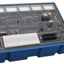
Electricity Lab
Bread Board Trainers
Bread Board Trainers
Product Description:
“Electricity Lab” is a versatile training kit for a laboratory. It is designed such that all the basic electrical circuits can be tested with the help of this trainer kit. The experiments given with training system develop mental starting from an introduction to the circuit, basic fundamentals and experiments on Ohm's Law, Magnetism, Relay, Power, Lenz's Law, Motors, Diode, Kirchoff's Law, R, L, C and many more. This simple training lab provides a strong foundation for future studies in electrical or electronics. This takes students from the basic of ohm's law, through simple series and parallel circuit analysis and into same elementary aspects of electronics where they will build circuits using capacitors and diodes. With this system a set of coils and cores are provided. These high quality coils (Labeled with number of turns) and laminated iron cores provides an effective introduction to electromagnetic theory.
Specifications:
• 01. Meters: 5 Nos.
• 1.1. AC Voltmeter : 15V
• 1.2. DC Voltmeter : 15V
• 1.3. Galvanometer : ± 250uA
• 1.4. DC Ampere Meter : 0.6Amp
• 1.5. DC Ampere Meter : 5A
• 02. Power Supply:
• 2.1. Power Supplies : 3, 6, 12Vat 3.5A
• 2.2. Power SupplyAC : 30Vat1A
• 2.3. Power SupplyDC : 5Vat100mA
• 03. Switch SPDT
• 04. Switch DPDT
• 05. Push switch
• 06. Logic Switches Two No. Push type
• 07. Relay 12VDCOne change over
• 08. Buzzer/Electric Bell
• 09. Transformer Input 6-0-6V and Output 6-0-6V
• 10. Bulb6VThree Nos.
• 11. Resistance 1E2/1W, 5E/5W, 50E/5W,100E/5W, 220E/2W, 470E/2W, 1K/1W, 100K/1W
• 12. Capacitance 1000MFD/25VTwo Nos.
• 13. Diode IN4007Two Nos.
• 14. LED5mm
• 15. Thermocouple
• 16. Potentiometer 10K
• 17. Breadboard 840Tie Points
• 18. Fuse Holder open type
• 19. Electromagnetic Induction&Transformer
• 20. Main Supply 230VAC, 50 Hz
Accessories:
• 1. Beaker 100ml - 1 No.
• 2. Patch Cords/ Connecting Leads - 12No s.
• 3. Rods/ Strips for - 1 No. each Copper, Tin, Al, Zinc,
• Glass Brass, Carbon, Iron, Acrylic,
• Lead, Stainless Steel
• 4. Magnets - 3Nos.( Bar Type-2, Horseshoe (U) type-1)
• 5. Coils - 1 No. 100 and 200 Turns
• 6. Crocodile Clips - 1 No. red and black
• 7. Battery/ Cell with holder - 2 Nos. 1.5 V
• 8. Glass Fuses - 10 Nos. 0.5A
• 9. Compass - 1 No.
• 10. Measuring Scale - 1No.
• 11. Insulated Disc - 1 No.
• 12. Motor Assembly - 1 No. including Armature,Rotor, Brush, Motor Support,
• Iron Fillings
• 13. Helix Assembly - 1 No.
• 14. Meter Demonstration - 1 No.
• 15. Core - 1 Set of U&I with Bolt
• 16. Aluminium Ring - 1 No.
• 17. Stand - 1 No. for motor action demonstration
• 18. IC - AND (IC7408), OR (Ic7432), NOT (7404) And EX-OR Gate (IC7486)
• 19. Multimeter - 1 No.
• 20. Soft Iron Piece - 1No.
Experiment Coverage: To Study/ Experiment the following:
• 01. Electricity by Chemical Action
• 02. Electricity by Heat
• 03. Electricity by Magnets
• 04. Conductors and Insulators
• 05. Resistor Colour Code
• 06. Resistors in series combination
• 07. Resistors in Parallel combination
• 08. Resistors in series and Parallel combination
• 09. Ohm's Law
• 10. Applying Ohm's Law
• 11. Kirchoff's Current Law or Junction Rule
• 12. Kirchoff's Voltage Law or Loop Rule
• 13. Linear & Non Linear Resistance
• 14. Measurement of Power
• 15. AC & DC Power
• 16. Fuses and Circuit Breakers
• 17. Heating Effect & the Fuse
• 18. Load in Series and Parallel Circuits
• 19. Cells Connections
• 20. Voltage in series & parallel Circuits
• 21. Current in series and parallel Circuits
• 22 Meter Movement
• 23 Meters in a Circuit
• 24. Charging and Discharging of Capacitors
• 25. Study of Diode
• 26. Full Wave Rectifier (optional)
• 27. The Contactor
• 28. Study of Relay
• 29. The Electric Bell
• 30 Magnets and Magnetism
• 31. Magnetic Field
• 32. Magnetic Properties
• 33. Magnetic Strength
• 34. Magnetic field around a conductor
• 35. Magnetic poles around a helix
• 36. Electromagnetic Strength
• 37. Electromagnetic Effect
• 38. Lenz’s Law
• 39. Self Inductance
• 40. Mutual Induction
• 41. Transformer Action
• 42. Transformer Ratio of Voltages
• 43. Transformer Phasing
• 44. Faraday's Law of Electromagnet Induction
• 45. Motor Action
• 46. The Electric Motor Generator
• 47. Generation of DC
• 48. Generation of AC
• 49. Permanent Magnet DC Motor
• 50. DC Series Motor
• 51. DC Shunt Motor
• 52. AC Universal Motor
• 53. AND Logic Gate with truth table
• 54. OR Logic Gate with truth table
• 55. NOT Logic Gate with truth table
• 56. X-OR Logic Gate with truth table
• 57. Convert a Galvanometer into voltmeter
• 58. Convert a Galvanometer into Ammeter
Note: Specifications are subject to change. Order Code can be different from Manufacturer’s Model No.
Free shipping to any address in South Africa
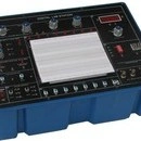
Digital Lab Station
Bread Board Trainers
Bread Board Trainers
Product Description:
DIGITAL LAB STATION is designed for the logic beginners to enhance the comprehension of basic logical theory. The digital lab covers regular digital circuits by solder-less interconnections on breadboard and as well as compitable with all optional modules through use of 2mm brass terminals and patch cords The design of the equipment is easy to operate and understand. It is equipped with various kinds of basic logic gates, debounced logical switches, LED indicators, DC power supply with short circuit protection, pulse generator and solderless breadboard. The unit housed in attractive enclosure is supplied with mains cord, patch cords, Instruction manual.
Learners in high schools, Polytechnic Colleges and Universities, can use the trainer as independent activity tool.
Experimental Coverage:
• 1. Logic gates operation
• 2. To prove De-morgan’s theorem With boolean logic equations
• 3. Binary to Gray code conversion
• 4. Gray code to Binary conversion
• 5. Binary to Excess-3 code conversion
• 6. Binary Adder and Subtractor
• 7. Binary Multiplier
• 8. EX-OR gate implementation
• 9. Application of EX-OR gate
• 10. Johnson Counter
• 11. To verify the dual nature of Logic Gates
• 12. Study of Flip-Flops RS, JK, D&T
• 13. Multiplexer and Demultiplexer
• 14. 4 Bit Binary up and down counter
• 15. Study of 8 to 3 Line Encoder
• 16. Study of 3 to 8 Line Decoder
• 17. Study of Shift Register (SIPO)
• 18. CMOS-TTL Interfacing
• 19. Study of Crystal oscillator
• 20. Study of pulse stretcher circuit
• 21. 4 Bit Ring Counter
• 22. Modulo 12 Counter By Direct Clearing
• 23. Decade counter
• 24. Shift Register SISO and PIPO
1. SOLDER LESS BREADBOARD : Interconnected nickel plated with a total of 2120 tie points in total, fitting all DIP sizes and components with lead and solid wire in diameter of AWG #22-30 (0.3 - 0.8mm)
2. DC POWER SUPPLY : Variable DC power :
• Positive output voltage: 0 to +15V
• Negative output voltage: 0 to – 15V
• Maximum output current: 300 mA
• Line regulation: < 0.05%/V (Ta=25°C)
• Load regulation: < 30 mV (Ta=25°C)
• Fixed power supply:
• Positive output voltage: 5V ± 0.25V
• Maximum output current: 1 Amp
• Line regulation: < 50 mV
• Load regulation: < 100 mV
• Negative output voltage: -5V ± 0.25V
• Maximum output current: 100 mA
• Line regulation: < 25 mV
• Load regulation: < 30 mV
• All DC Power Supplies are equipped with
• short circuit protection
3. FUNCTION GENERATOR : Frequency ranges:
• 1Hz - 11Hz
• 10Hz - 110Hz
• 100Hz - 1K1KHz
• KHz - 11KHz
• 10KHz - 110KHz
• Sine wave output: 0 to 8 Vp-p variable
• Triangle wave output: 0 to 6 Vp-p variable
• Square wave output: 0 to 8 Vp-p variable
4. DIGITALVOLTMETER : 3 1/2 digits LED display 4 ranges:
• 1 - 199.9V full scale
• 2 - 19.99V full scale
• 3 - 1.999V full scale
• 4 - 199.9mV full scale
• Input impedance: 10 Meg. Ohm for any range
5.TWO DIGIT SEVEN SEGMENT LED DISPLAY COMMON CATHODE
6 FOUR POINTTIP/ BANANA SOCKET / BNC SOCKET EXCHENGE ADAPTERS
7. EIGHT BUFFERED LED DISPLAY
8. EIGHT DATA SWITCH
9. TWO FUNCTION SWITCHES
10 TWO PULSE SWITCH
Free shipping to any address in South Africa