
Supply, Repair and Calibrate Electrical, Electronic and Telecom Test Equipment, Radio Planning and Optimization Services for wireless network technologies.
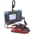
Aitelong SAT-AC Battery Conductance Tester
Miscellaneous
Aitelong SAT-AC Battery Conductance Tester
Product Description
SAT-AC Series battery Conductance Tester is a multi-function and portable digital data storage measurement instrument to test battery running condtion and parameters quickly and precisely. it can display and record many key parameters for multi-groups like as battery string and each battery cell's voltage, conductance, connecting strip resistance, battery's internal resistance and so on; offer the ability to distinguish battery's condition effectively and accurately; compose with intelligent PC measurement analyzing software, user can track battery's decay trend, and alarm beforehand to help technician and administrators process according to status.
Key Features
• High precision online testing, Automatically switch the testing range, large capacity data storage
• 320 x 240 LCD
• Smart and easy-to-use design, one person can conduct all the tests
• Transmit the testing data to PC by Micro SD card to carry out analysis of battery according to the history data.
• Display value of voltage, conductance, internal resistance.
• Enhanced over voltage protection function.
• Automatically recover the over current protection function.
• Use the SOC chip to improve the tester stability.
• Powered by a large capacity Lithium call battery or adapter.
• Low battery warning to guarantee precision testing.
• Automatic testing mode for user's convenience.
• Powerful PC software to manage the data testing:
- Automatically analyze the battery's SOH (State-of-health)
- Building the history record database, describes the battery's life span curve
Functions
• Test the battery voltage and conductance online.
• Battery conductance and voltage out of range alarm.
• All the battery parameters are marked by group No. to make the user manage the data expediently.
• PC software analyze the battery to carry out tracking "historical analysis" of battery system.
Technical Parameter
Model
SAT-AC650
SAT-AC350
Conductance Test Range
100S-19990S
100S-9999S
Voltage Test Range
0.000 ~ 20.0 00V conductance & Voltage only
0.000 ~ 16.000V conductance voltage
Measurement Precision
Conductance: ±0.5%rdg ±6dgt
Voltage: ±0.2% ±6dgt
Conductance: ±0.5%rdg ±dgt
Voltage: ±0.2%rdg ±6dgt
Power Supply
10.8V, 2000mAh, Rechargeable Lithium Battery
Watt Consumption
Works for 8 hours Continuously
Storage Capacity
2G Micro SD
Display
320 x 240 matrix dot LCD
Size
210mm x 140mm x 60mm
Weight
1.2 Kg
Working Temperature
-500C - -+600C
Humidity
90% RH
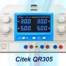
Citek-QR SERIES TRIPLE OUTPUT ADJUSTABLE DC POWER SUPPLY
Power Supplies For Students
TRIPLE OUTPUT ADJUSTABLE DC POWER SUPPLY
Citek-QR SERIES
Features
• Output off function
• Triple independent DC outputs. Two adjustable and one fixed output.
• Independent, series and parallel variety output
• Constant voltage and constant current
• Low ripple and noise
• Four LED displays with 3 digits, selectable for two sets output voltage and current display simultaneously
• 16 hours continuous output with full load
• Auto tracking output
Specifications
Line regulation
CV 1 x 10⁻⁴ CC 2 x 10⁻³ + 3mA
Load regulation
CV 1 x 10⁻⁴ + 4 mV CC 2 x 10⁻³ + 5mA
Ripple & noise
CV 1mV rms CC 3mA rms
Display accuracy
± 0.5%Rdg+2digits
Input voltage
110~127VAC ± 10%, 220~240 ± 10% Switchable
Model
Independent
Output
Series
Output
Parallel
Output
Dimensions
(W x H x D)
Weight
(Kg)
Citek-QR302
CH1 0~30V/0~2A
CH1+CH2
0~60V/0~2A
CH1/CH2
0~30V/0~4A
250 x 135 x 300 mm
8.2
Citek-QR303
CH2 0~30V/0~2A
CH3 1A/5V
CH1+CH2
0~60V/0~3A
CH1//CH2
0~30V/0~6A
250 x 135 x 300 mm
8.2
Citek-QR305
CH1 0~30V/0~5A
CH2 0~30V/0~5A
CH3 1A/5V
CH1+CH2
0~60V/0~5A
CH1//CH2
0~30V/0~10A
250 x 135 x 300mm
9
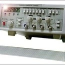
CI5081639B Function Generator
Function Generator
Function Generator
Features:
• Multi waveforms:Sine,Triangle,Square,and etc
• Built-in 5 digits counter(up to 15MHz equal accurate)
• DC offset,symmetry continuously adjustable
• VCF input
• Economical type, low cost
Specifications:
Technical Data
CI5081639B
Main output
Output frequency
0.06Hz~6MHz
Output waveforms
Sine wave,Square wave,Triangle wave and etc.
Output impedance
50Ω±10%
Output amplitude
≥20Vp-p(No Load)
Output attenuation
0dB/20dB/40dB/60dB
DC offset
0~±10V adjustable
Symmetry
10%~90%
Sine wave
Distortion factor
10Hz~100kHz<1%
Frequency response
0.2Hz~100kHz≤±0.5dB 100kHz~2MHz≤±1dB
Square wave
Rise or fall time
<100ns
TTL output
Rise or fall time
≤1μs
Low level
≤0.4V
High level
≤3.5V
Impedance
600Ω
VCF
Input voltage
-5V~0V
Input impedance
10KΩ±10%
Counter
Display
5 digits
Frequency range
1Hz~15MHz
Input impedance
≥1MΩ/20pF
Sensitivity
100mVrms
Accuracy
0.1Hz/1Hz/10Hz/100Hz
Error
≤0.003%±1 digit
Max.input voltage
150V(AC+DC)(with attenuator)
Input attenuation
0dB/20dB
Power supply
110~127VAC±10%,220~240VAC±10%,50Hz±2Hz/60Hz±2Hz
Dimension(W×H×D)
310×80×230mm
Weight
1.75kg
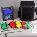
Citek 50830B Grounding resistance / Soil resistivity tester
Ground Resistance Testers
Product Description:
The Citek 50830B grounding resistance / soil resistivity tester is designed for on-site measurement of grounding resistance, soil resistivity, ground voltage, AC voltage is carefully designed and manufactured using the latest digital micro-processing technology, precise 4-wire method, 3-wire method and simple 2-wire measurement of grounding resistance, import the FFT (Fast Fourier Transform) technology, AFC (automatic frequency control) technology, has a unique anti-jamming capability and ability to adapt to the environment, repeat the test is consistent, to ensure many years measurements of high precision, high stability and high reliability. Widely used in electricity, telecommunications, meteorology, oil, construction, mine and industrial electrical equipment such as grounding resistance, soil resistivity, ground voltage, AC voltage measurement.
The Citek 50830B grounding resistance / soil resistivity tester by the composition of the host, monitoring software, test leads, auxiliary grounding rods, communications lines. Host large LCD display, blue screen backlight, bar graph indication at a glance. Can store 300 sets of data, monitoring software, historical inquiry and online real-time monitoring capabilities, dynamic display, alarm indication, with historical data to read, access, save, report, print and other functions.
Technical Specifications
Base Conditions and Working Conditions
Influence Quantity
Base Condition
Working Conditions
Remark
Ambient Temp
23℃±1℃
-10℃-40℃
----
Ambient Humidity
40%-60%
<80%
----
Working Voltage
9V±0.1V
9V±1.5V
rC、rP
Auxiliary Earth Resistance
<100Ω
<30kΩ
----
Interference Voltage
no
<20V
----
Interference Current
no
<2A
Electrode Distance when measuring R
a>5d
a>5d
----
Electrode Distance when measuring ρ
a>20h
a>20h
----
General Specification
Function
Measurement of 2/3/4-pole earth resistance, soil resistivity, earth voltage, AC voltage
Power Supply
DC 9V(Zi-Mn dry battery R14S 1.5V 6 PCS, continuous standby for 300 hours )
Measurement Range
Earth Resistance: 0.00Ω-30.00kΩ
Soil Resistivity: 0.00Ωm-9000kΩm
Measuring Mode
Precise 4-pole measurement, 3-pole measurement, simple 2-pole measurement
Measuring Method
Earth Resistance: rated current change-pole method, measurement current 20mA Max
Soil Resistivity: 4-pole measurement (Wenner method)
Earth Voltage: average rectification(between P(S)-ES)
Test Frequency
128Hz/111Hz/105Hz/94Hz(AFC)
Short-circuit Test Current
AC 20mA max
Open-circuit Test Current
AC 40V max
Test Voltage Wave
Sine wave
Electrode DistanceRange
Can be set 1m-100m
Shift
Earth Resistance: 0.00Ω-30.00kΩ, automatic shift
Soil Resistivity: 0.00Ωm-9000kΩm, automatic shift
Backlight
Blue screen backlight, suitable for dim places
Display Mode
4-digital super-large LCD display, blue screen backlight
Measuring Indicator
During measurement, LED flash indicator, LCD count down display, progress bar indicator
LCD Frame Dimension
128mm×75mm
LCD Window Dimension
124mm×67mm
Dimension
L×W×H: 215mm×190mm×95mm
Standard Test Wire
4 wires: each for red 20m, black 20m, yellow 10m, and green 10m
Simple Test Wire
2 wires: each for red 1.6m and black 1.6m
Auxiliary Earthing Rod
4 rods: Φ10mm×150mm
Measuring Rate
Earth voltage: about 3 times/second
Earth resistance, soil resistivity: about 5 seconds/time
Measuring Times
Over 5000 times (Short-circuit test, interval time should be at least 30 seconds)
Line Voltage
below AC 600V
RS232 Interface
Possess RS232 interface, software supervision, storage data can be uploaded to computer, saved or printed.
Communication Wire
One piece of RS232 communication wire, with length 1.5m
Data Storage
300 sets, “MEM” icon storage indicator, flash display “FULL” icon to indicate storage is full
Data Hold
Data hold function: “HOLD” icon display
Data Access
Data read function: “READ” icon display
Overflow Display
Exceeding measuring range overflow function: “OL” icon display
Interference Test
Recognize interference signal automatically, “NOISE” icon display when interference voltage exceed 5V
Auxiliary Earthing Test
Can measure auxiliary earth resistance, 0.00KΩ-30kΩ(100R+rC<50kΩ, 100R+rP<50kΩ)
Alarm Function
When measuring value exceeds alarm setting value, there is “Toot-toot-toot” alarm hint
Battery Voltage
When battery voltage decreases to about 7.5V, battery voltage low icon will display, reminding to replace battery.
Power Consumption
Standby: about 20mA (Backlight shut off)
Boot and with backlight: about 45mA (25mA without backlight)
Measurement: about 100mA (Backlight shut off)
Weight
Total weight: 4.5kg (including package)
Tester: 1443g (including battery)
Tesing wires: 1560g
Auxiliary earthing rods: 935g (4pcs)
Working Temperature & Humidity
-10℃-40℃, below 80%rh
Storage temperature & humidity
-20℃-60℃, below 70%rh
Overload Protection
Measuring earth resistance: between each interfaces of C(H)-E、P(S)-ES,AC 280V/3 seconds
Insulation Resistance
Over 20MΩ (between circuit and enclosure it is 500V)
Withstanding Voltage
AC 3700V/rms (Between circuit and enclosure)
Electromagnetic Features
IEC61326(EMC)
Protection Type
IEC61010-1 (CAT Ⅲ 300V、CAT IV 150V、Pollution 2), IEC61010-031, IEC61557-1 (Earth resistance), IEC61557-5 (Soil resistivity), JJG 366-2004
Intrinsic error and performance indicators under base conditions
Category
Measurement Range
Intrinsic Error
Resolution
Earth Resistance
(R)
0.00Ω-30.00Ω
±2%rdg±3dgt
0.01Ω
30.0Ω-300.0Ω
±2%rdg±3dgt
0.1Ω
300Ω-3000Ω
±2%rdg±3dgt
1Ω
3.00kΩ-30.00kΩ
±4%rdg±3dgt
10Ω
Soil Resistivity
(ρ)
0.00Ωm-99.99Ωm
According to the precision of R
(ρ=2πaR
a:1 m-100m,
π=3.14)
0.01Ωm
100.0Ωm-999.9Ωm
0.1Ωm
1000Ωm-9999Ωm
1Ωm
10.00kΩm-99.99kΩm
10Ωm
100.0kΩm-999.9kΩm
100Ωm
1000kΩm-9000kΩm
1kΩm
Earth Voltage
AC 0.0-600V
±2%rdg±3dgt
0.1V
Accessories
Tester
1 PC
Tester Bag
1 PC
Auxiliary Earthing Rod
4 PCS
Standard testing Wire
4 wires: each for red 20m, black 20m, yellow 10m, and green 10m
Simple testing Wire
2 wires: each for red 1.6m and black 1.6m
Zinc-manganese Dry Battery
6 PCS (R14S 1.5V)
Monitoring Software Disk
1 Copy
RS232 Communication Cable
1 PC
Manual/Warranty Card/Qualification Certificate
1 Copy